Direct Fuel Injection
Page 3B-66 90-8M0050731 MAY 2011
Tube Ref No. Description Where Used Part No.
95
2-4-C with Teflon Fuel injector O-rings and screw threads 92-802859A 1
Description Nm lb‑in. lb‑ft
Screw 8 70
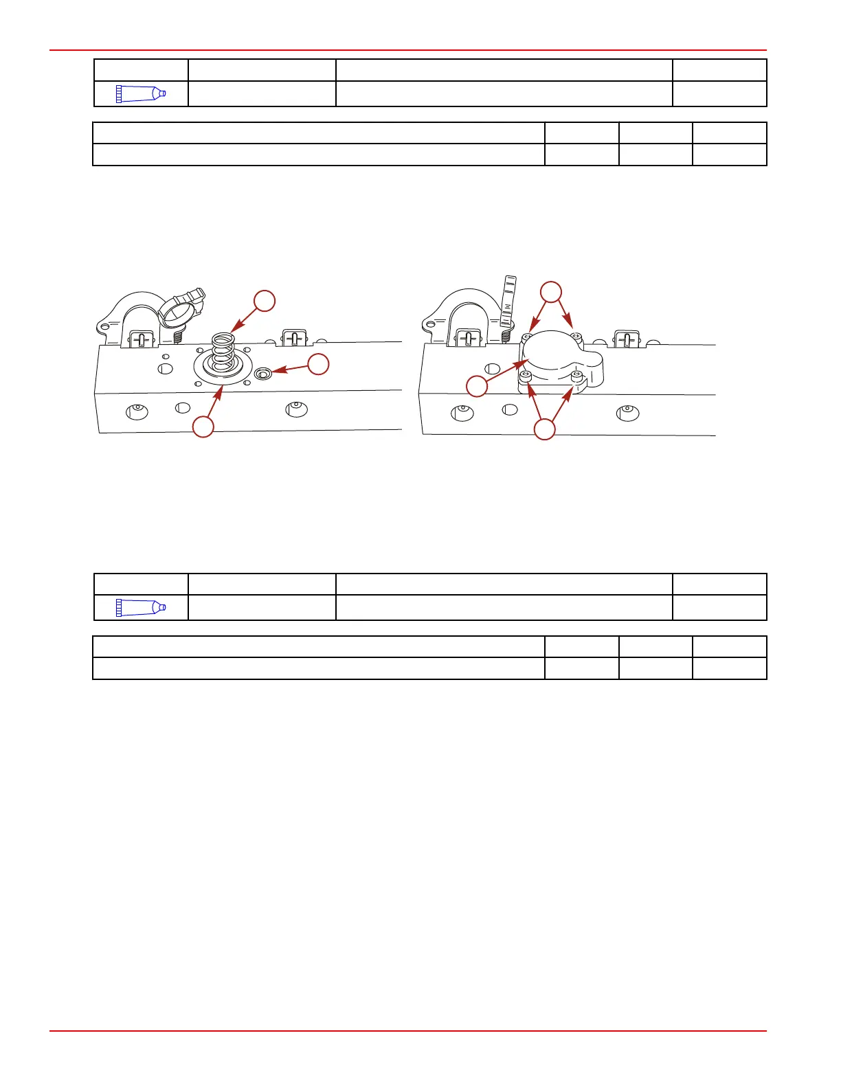
Tracker Valve Installation
1. Lubricate the tracker diaphragm and O‑ring with 2‑4‑C with Teflon.
2. Lubricate the screw threads with 2‑4‑C with Teflon.
3. Install the tracker diaphragm, spring, and O‑ring onto the fuel rail.
4. Install the cover and secure with four screws. Tighten the screws to the specified torque.
a - Diaphragm
b - Spring
c - O‑ring
d - Cover
e - Screws
Tube Ref No. Description Where Used Part No.
95
2-4-C with Teflon Tracker diaphragm, O-ring, and screw threads 92-802859A 1
Description Nm lb‑in. lb‑ft
Screw (4) 8 71
Air Pressure Regulator Installation (S/N 0T178500 and Above)
1. Install new O‑rings onto the air pressure regulator.
2. Lubricate the air pressure regulator O‑rings with 2‑cycle Premium Outboard Oil.
3. Lubricate the screws with 2‑4‑C with Teflon.

 Loading...


