Direct Fuel Injection
90-8M0050731 MAY 2011 Page 3B-57
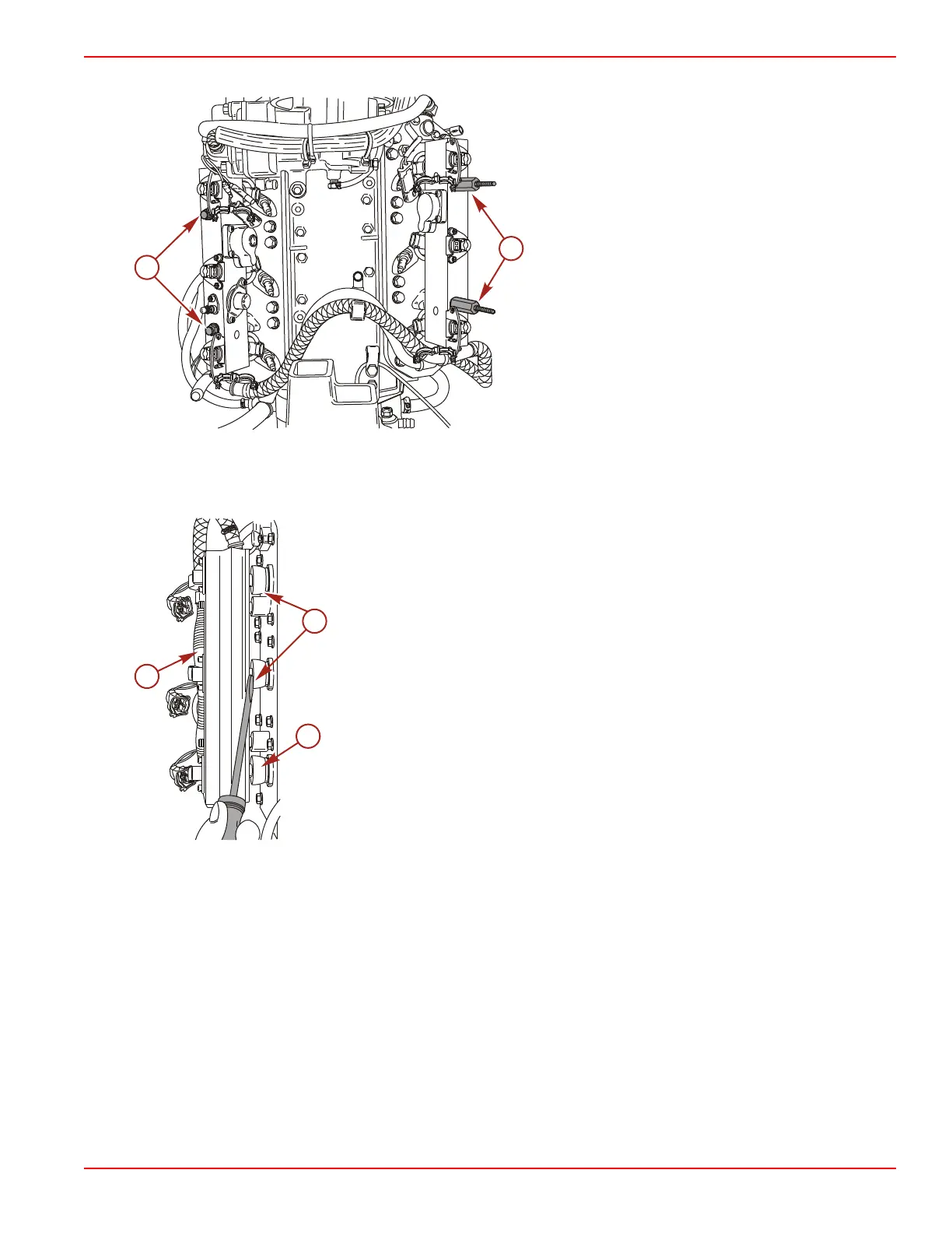
9. Remove the two nuts and two coil plate spacers securing the fuel rail to the cylinder head.
a - Nut
b - Coil plate spacer
10. As the fuel rail is removed, use a flat tip screwdriver to ensure the direct injectors remain in the cylinder head.
NOTE: The direct injectors should remain in the cylinder head. The direct injectors have a Teflon seal which may expand
when the direct injector is removed from the cylinder head. This expansion may cause installation difficulty or require the
replacement of the seal.
a - Fuel rail
b - Direct injectors
The starboard fuel rail contains three fuel injectors and a tracker valve.
The port fuel rail contains three fuel injectors, one fuel regulator, and one air regulator.
NOTE: Each fuel/air inlet or outlet hose adapter has two O‑ring seals. These O‑rings should be inspected for cuts or abrasions
and replaced as required when the fuel rail is disassembled for cleaning.
Fuel Injector Removal
1. Remove the two screws securing the injector to the fuel rail.

 Loading...


