Powerhead
Page 4A-24 90-8M0050731 MAY 2011
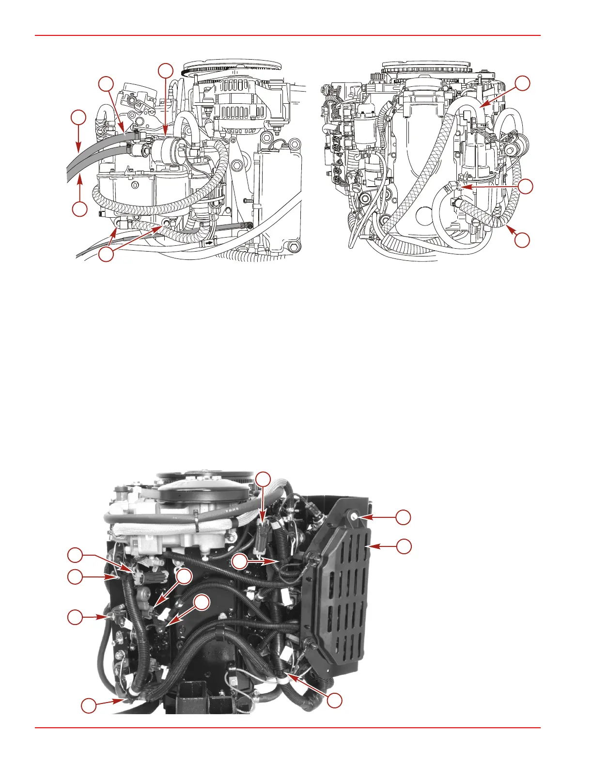
10. Remove three mounting bolts and remove the separator.
a - Fuel lift pump inlet hose
b - VST vent hose
c - Mounting bolts (M8 x 35) (3) (hidden)
d - Ground lead
e - High‑pressure fuel outlet hose
f - Low‑pressure fuel return hose
g - VST fuel inlet hose
Electrical Plate and Harness Removal
1. Remove the electrical plate cover.
2. Disconnect the temperature sensor connectors.
3. Remove the spark plug boots from the spark plugs.
4. Disconnect the fuel injector connectors.
5. Disconnect the direct injector connectors on the starboard fuel rail.
6. Disconnect the wiring harness retainers.
a - Screw and bushing
b - Electrical plate cover
c - Temperature sensor
connectors (2)
d - Direct injector connectors
(6)
e - Fuel injector connectors
(6)
f - Spark plug boots (6)
g - Wiring harness retainers
(4)

 Loading...


