Ignition
90-8M0050731 MAY 2011 Page 2A-23
Throttle Position Sensor Specifications
Model year 2001 and newer
Idle 0.4–1.3 VDC
Wide‑open throttle 4.0–4.7 VDC
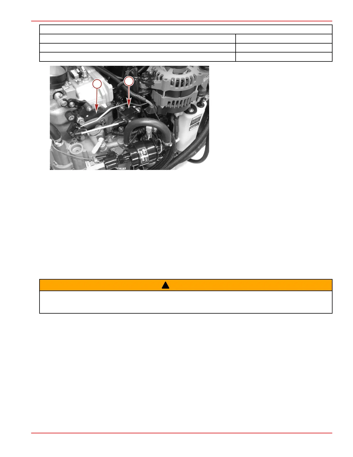
a - Throttle position sensor
b - Throttle cam
Throttle Position Sensor (TPS) Troubleshooting
If the throttle position sensor is out of the intended operating range when the engine is started, the propulsion control module
(PCM) will sense that the throttle position sensor (TPS) has failed. The warning horn will sound, check engine light will illuminate,
CDS will indicate failed TPS, and the engine will go into RPM reduction. When the engine is started, the throttle arm on the engine
must be against the throttle stop screw. Do not move throttle or fast idle control lever forward.
• Check the throttle cable adjustment. The throttle stop screw on the throttle arm must be against the throttle stop on the cylinder
block when the engine is started. Preload the throttle cable barrel one or two turns if necessary.
• Verify the driver is not pushing on the throttle (if foot throttle is used) or advancing the throttle only on the control box.
• Check the throttle cam to roller adjustment. If the roller is not down in the pocket/valley area on the cam, there is a tendency
for the roller to ride up or down on the cam which causes the TPS link arm to push/pull on the TPS lever resulting changing
values.
Throttle Position Sensor (TPS) Removal and Installation
Throttle Position Sensor Removal
!
WARNING
Performing service or maintenance without first disconnecting the battery can cause product damage, personal injury, or death
due to fire, explosion, electrical shock, or unexpected engine starting. Always disconnect the battery cables from the battery
before maintaining, servicing, installing, or removing engine or drive components.
1. Disconnect both battery cables from the batteries.
2. Disconnect the engine harness from the TPS.
3. Remove the TPS link arm assembly from the TPS lever.
4. Remove the three M6 x 25 screws securing the TPS and cover to the crankcase.
Throttle Position Sensor Installation
1. Secure the TPS to the crankcase with three M6 x 25 screws. Tighten the screws to the specified torque.

 Loading...


