Powerhead
Page 4A-70 90-8M0050731 MAY 2011
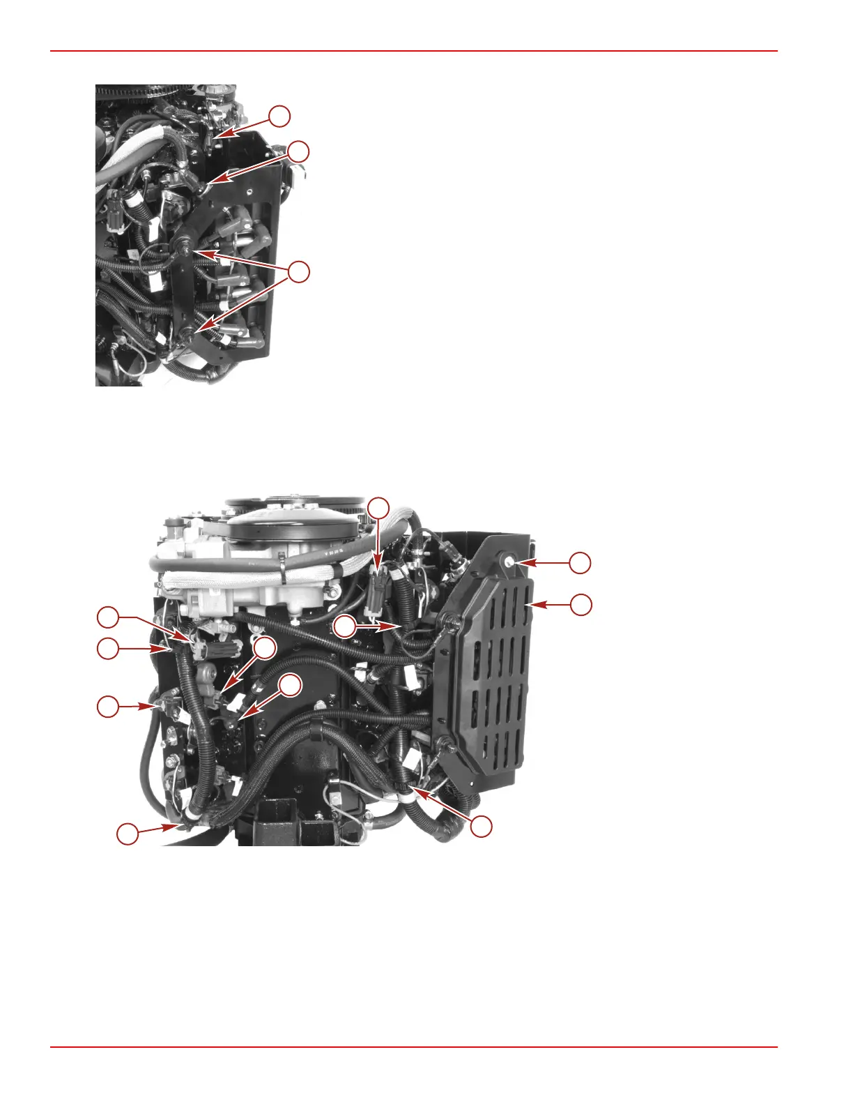
15. Install the screw securing the electrical plate cover.
a - Crankshaft position sensor connector
b - Water pressure sensor
c - Nut (M8)
16. Connect the wiring harness retainers.
17. Connect the direct injector connectors on the starboard fuel rail.
18. Connect the fuel injector connectors.
19. Install the spark plug boots onto the spark plugs.
20. Connect the temperature sensor connectors.
a - Screw and bushing
b - Electrical plate cover
c - Temperature sensor
connectors (2)
d - Direct injector connectors
(6)
e - Fuel injector connectors
(6)
f - Spark plug boots (6)
g - Wiring harness retainers
(4)
Powerhead Installation on the Pump Unit
1. Install the lifting eye into the flywheel.
2. Lift powerhead high enough to allow removal of the powerhead from the stand. Remove the powerhead from the stand, being
careful not to damage gasket surface of adapter plate.
IMPORTANT: DO NOT apply lubricant to top of driveshaft as this will prevent driveshaft from fully engaging into crankshaft.
3. Apply a small amount of Special Lubricant 101 onto the driveshaft splines.

 Loading...


