Powerhead
90-8M0050731 MAY 2011 Page 4A-71
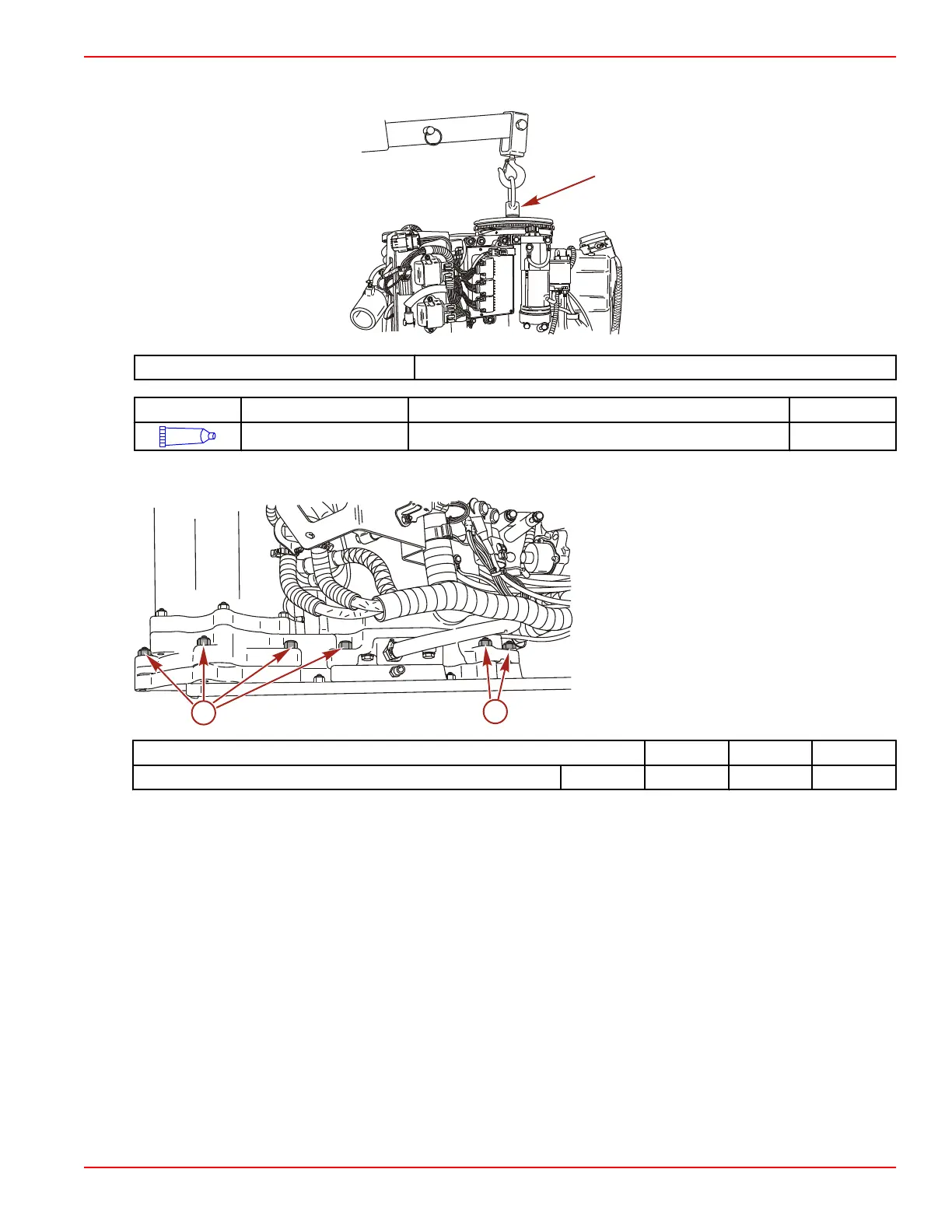
4. Lower powerhead onto pump unit. It may be necessary to turn flywheel (aligning crankshaft splines with driveshaft splines)
so that powerhead will be fully installed.
Lifting Eye 91‑ 90455 1
Tube Ref No. Description Where Used Part No.
34
Special Lubricant 101 Driveshaft splines 92-802865Q02
5. Install eleven nuts which secure powerhead to exhaust extension plate/driveshaft housing. Tighten the nuts in three
progressive steps until the final torque specification is reached.
a - M10 nuts (11)
Description Nm lb‑in. lb‑ft
M10 nuts (11) Final 47 35
6. Disconnect the hoist from lifting eye and remove the lifting eye from flywheel.
7. Install the plastic cap into the center of the flywheel cover.
8. Connect the positive battery cable to the starter solenoid.
9. Connect the negative battery cable to the lower front starter mounting bolt.
10. Connect the remote oil tank pressure hose.

 Loading...


