Timing, Synchronizing, and Adjusting
Page 2C-4 90-8M0050731 MAY 2011
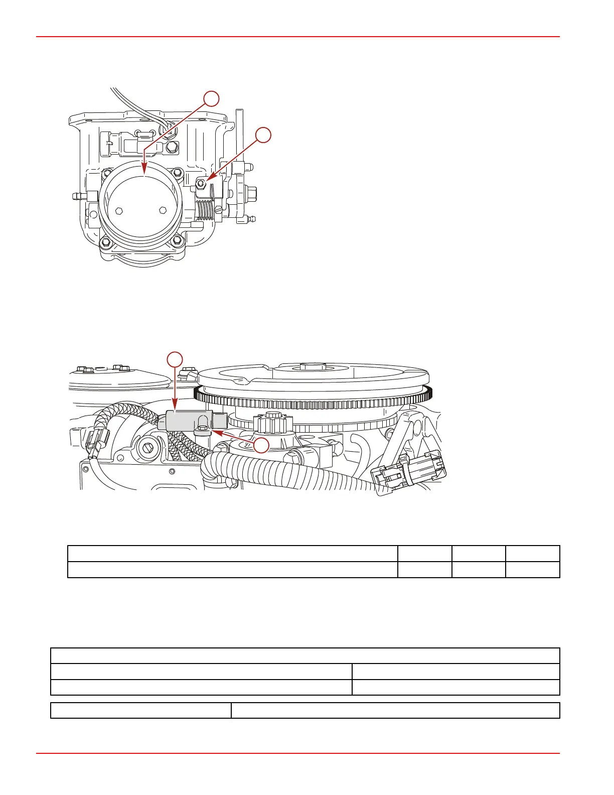
Throttle Plate Stop Screw
IMPORTANT: Do not adjust the throttle plate stop screw from the factory setting. However, should the throttle plate require
adjustment, use the throttle plate stop screw to set the throttle plate clearance to 0.7937 mm (0.031 in.) with a #68 drill bit.
a - Throttle plate stop screw
b - Throttle plate clearance
Crankshaft Position Sensor Air Gap
IMPORTANT: The crankshaft position sensor air gap (between flywheel tooth and sensor) is not adjustable. Visually inspect sensor
for damage from foreign debris. Replace sensor as required.
1. Remove flywheel cover. Refer to Section 2A - Flywheel Cover Removal and Installation.
2. Inspect for damage or debris.
a - Crankshaft position sensor
b - Bracket screw
Description Nm lb‑in. lb‑ft
Crankshaft position sensor bracket screw 5 44
3. Install flywheel cover.
Throttle Position Sensor (TPS) Adjustment
The TPS is not adjustable. The TPS position can be monitored with the computer diagnostic system. Voltage change should be
smooth from idle to wide‑open throttle. If the voltage change is erratic, the TPS is defective.
Throttle Position Sensor Specifications
Idle 0.4–1.3 VDC
Wide‑open throttle 4.0–4.7 VDC
Computer Diagnostic System (CDS) Order through SPX

 Loading...


