Direct Fuel Injection
90-8M0050731 MAY 2011 Page 3B-33
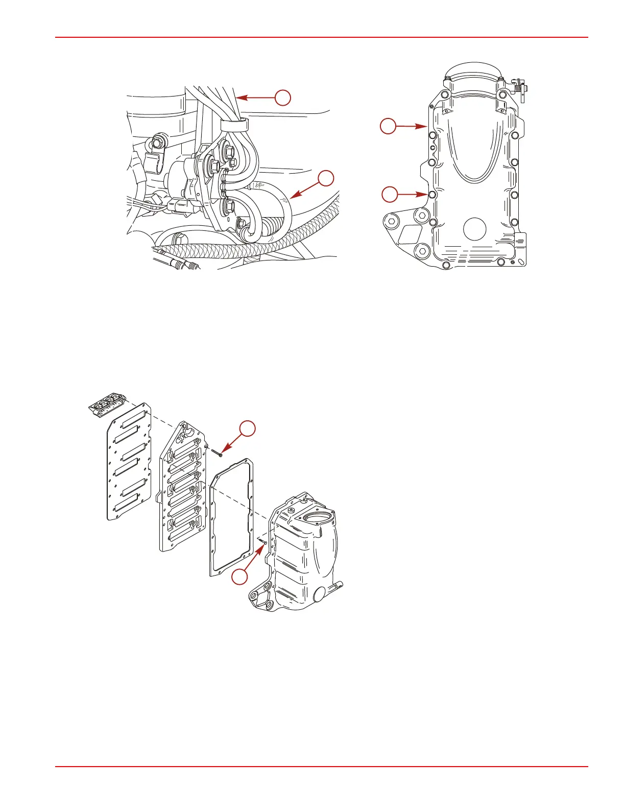
15. Remove the twelve bolts securing the air management assembly to the crankcase and remove the assembly.
a - Oil outlet hoses (6)
b - Oil inlet hose (1)
c - Air management
d - Bolts (1/4‑20 x 1‑1/2, flange) (12)
Reed Block Assembly Removal
1. Remove the two screws securing the air plenum to the reed plate assembly.
2. Remove the 12 screws securing the reed blocks to the reed plate assembly.
a - Screw (1/4‑20 x 7/8 in.) (12)
b - Screw (M4 x 16) (2)
Throttle Body Assembly Removal
NOTE: The throttle body assembly is calibrated and preset at the factory. Other than complete assembly removal from the air
plenum, no further disassembly should be made.

 Loading...


