Direct Fuel Injection
Page 3B-32 90-8M0050731 MAY 2011
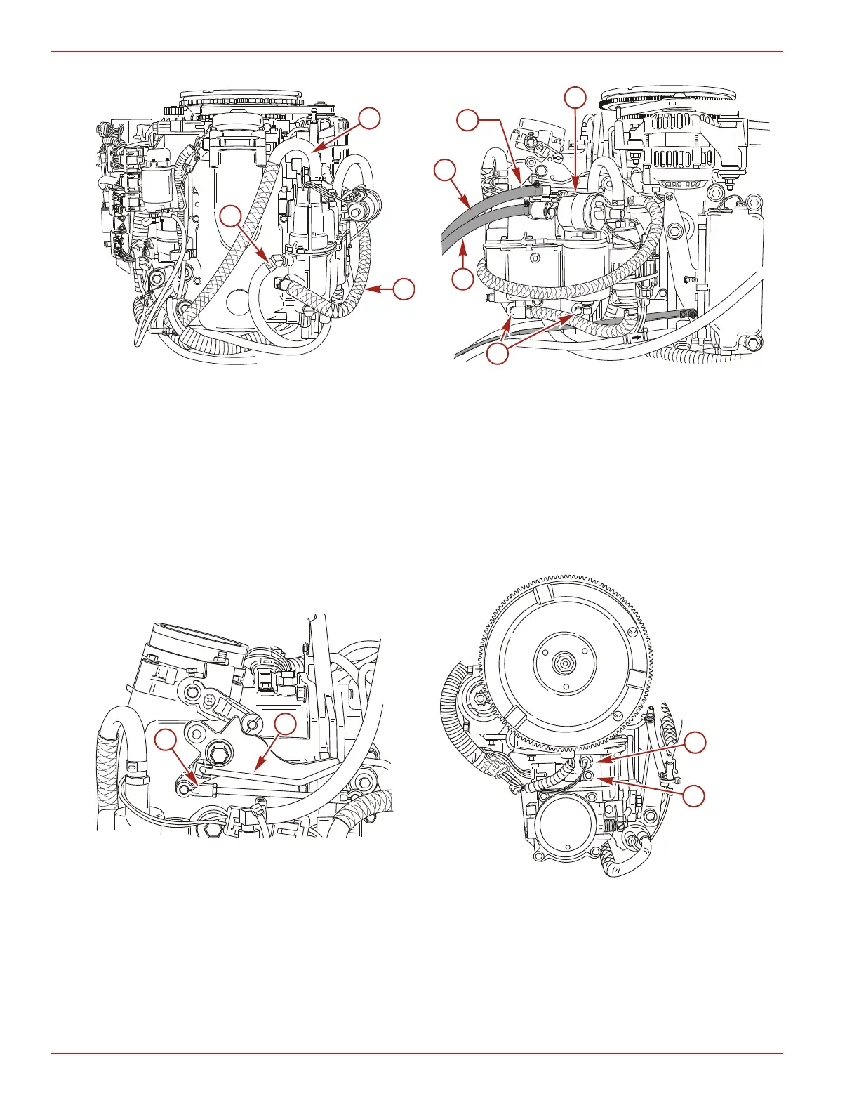
9. Remove the three mounting bolts and remove the separator.
a - Fuel inlet hose to fuel lift pump
b - Vapor separator vent hose
c - Fuel outlet hose
d - Fuel return hose
e - Fuel inlet hose
f - Mounting bolts (3)
g - Ground lead
10. Disconnect the throttle cam link rod and the throttle position sensor (TPS) link rod.
11. Disconnect the manifold absolute pressure (MAP) sensor from the air management assembly.
12. Disconnect the engine harness connector from the manifold air temperature (MAT) sensor connector.
a - Throttle link rod
b - TPS link rod
c - MAP sensor
d - MAT sensor
13. Disconnect the oil hoses from the oil pump.
14. Remove and plug the oil inlet hose to the oil pump.

 Loading...


