Direct Fuel Injection
Page 3B-34 90-8M0050731 MAY 2011
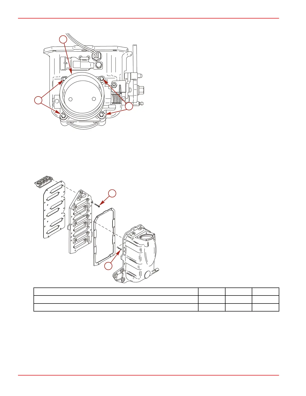
Remove the four screws securing the throttle body assembly to the air plenum. Remove the throttle body assembly.
a - Screw (4)
b - Throttle body assembly
Air Management Assembly and Installation
1. Remove the old gasket material from the mating surfaces of the reed blocks, reed block plate, and air plenum.
2. Install a new gasket onto the reed block plate. Secure each reed block to the reed block plate with two 1/4‑20 x 7/8 in. screws.
Tighten the screws to the specified torque.
3. Install a new gasket onto the air plenum. Secure the reed block plate to the air plenum with two M4 x 16 screws. Tighten the
screws to the specified torque.
a - Screw (1/4‑20 x 7/8 in.) (12)
b - Screw (M4 x 16) (2)
Description Nm lb‑in. lb‑ft
Screw (1/4‑20 x 7/8 in.) 11.5 102
Screw (M4 x 16) 2.5 22
4. Install a new O‑ring onto the throttle body. Secure the throttle body assembly to the air plenum assembly with four M6 x 40
screws. Tighten the screws to the specified torque.
5. Install the MAP sensor and bracket onto the air plenum assembly. Secure the bracket with a M6 x 16 screw. Tighten the screw
to the specified torque.
6. Install an O‑ring onto the manifold air temperature (MAT) sensor.

 Loading...


