Pump Unit
Page 5A-26 90-8M0050731 MAY 2011
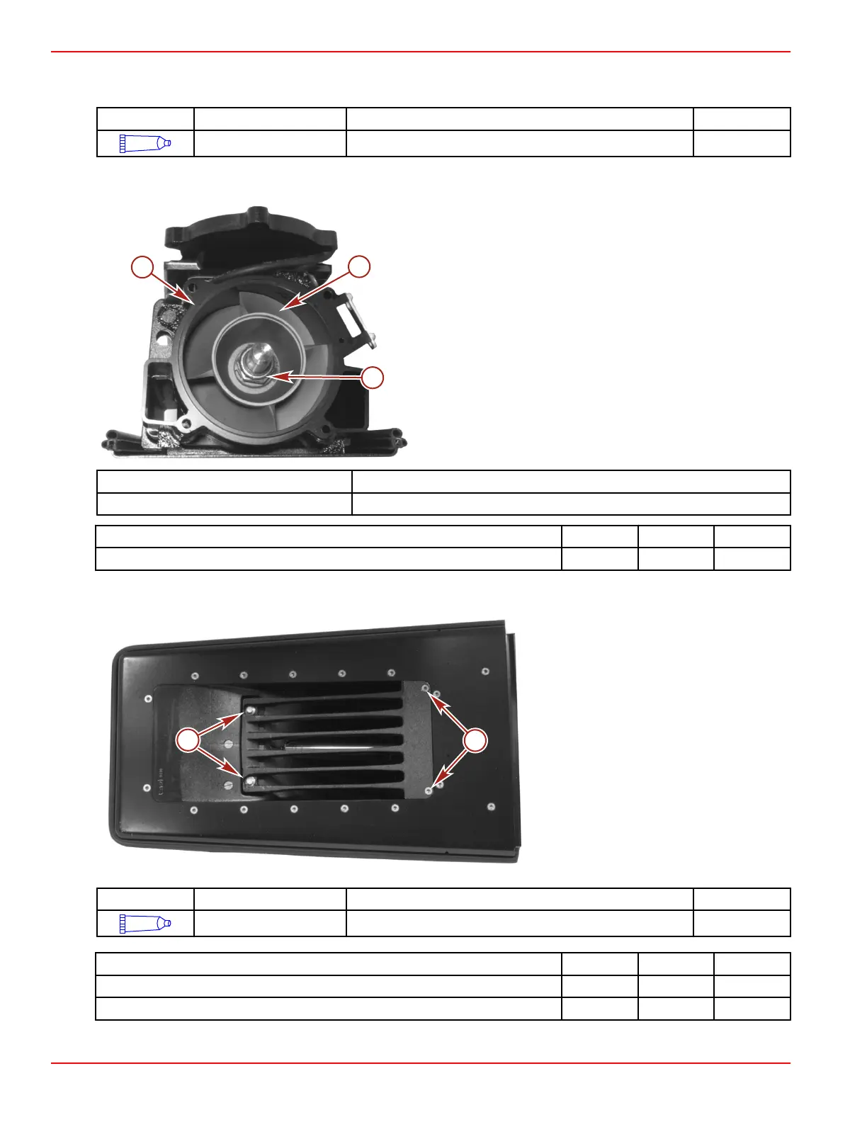
2. Lubricate the wear ring O‑rings with Special Lubricant 101. Install the O‑ring into the counterbore. Install the O‑ring onto the
wear ring.
Tube Ref No. Description Where Used Part No.
34
Special Lubricant 101 Impeller shaft splines and wear ring O-rings 92-802865Q02
3. Install the wear ring onto the jet drive housing.
4. Install the impeller and nut onto the impeller shaft. Tighten the impeller nut to the specified torque.
a - Wear ring
b - Impeller
c - Nut (1¼‑12)
Impeller Nut Socket 91‑850297
Impeller Shaft Wrench 91‑832093A 1
Description Nm lb‑in. lb‑ft
Impeller nut (1¼‑12) 203 150
5. Install the inlet screen. Apply Loctite 242 Threadlocker to threads of screws. Tighten the screws and bolts to the specified
torque.
a - Screw (M8 x 25) (2)
b - Screw (M6 x 20) (2) (30 Torx)
Tube Ref No. Description Where Used Part No.
66
Loctite 242 Threadlocker Inlet screen screws and bolts 92-809821
Description Nm lb‑in. lb‑ft
Inlet screen screws (M6 x 20) (2) (30 Torx) 8.5 75
Inlet screen screws (M8 x 25) (2) 22.5 16.6
6. Install the stator. Apply Loctite 271 Threadlocker to threads of four screws. Tighten the screws to the specified torque.

 Loading...


