Direct Fuel Injection
90-8M0050731 MAY 2011 Page 3B-77
Tube Ref No. Description Where Used Part No.
7
Loctite 271 Threadlocker Air compressor end cap screw threads 92-809819
Description Nm lb‑in. lb‑ft
Screw (carbon steel) (M6 x 20) 17 150
Screw (stainless steel) (M6 x 20) 11.5 100
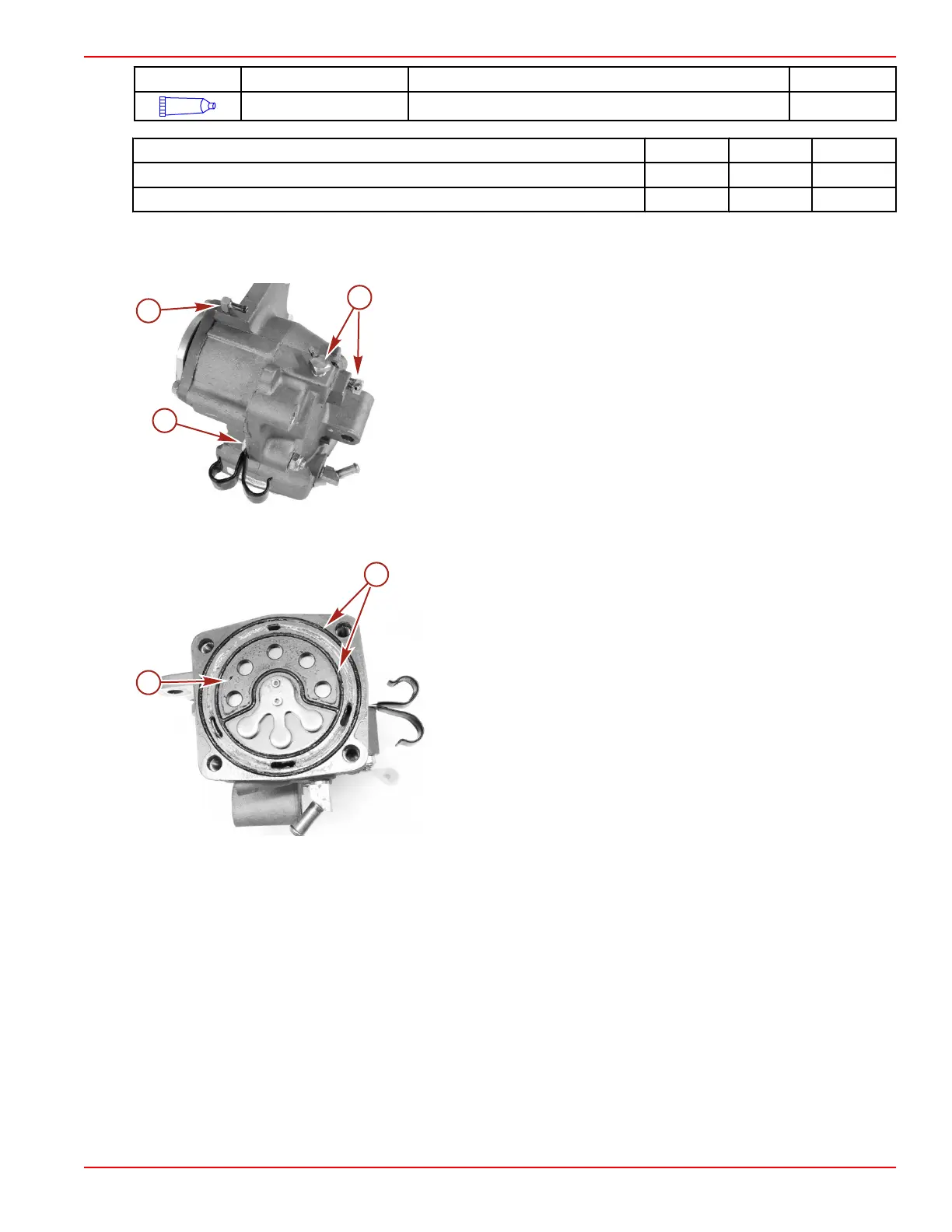
10. Install the two check valves onto the air compressor.
11. Install and secure the two J‑clamps, if used, to the air compressor with a bolt and nut. Tighten the bolt and nut securely.
NOTE: Later models will use either a plastic clip or cable ties in place of the two J‑clamps.
a - Bolt and nut securing the two J‑clamps
b - Oil supply fitting
c - Check valves (2)
12. Install the O‑rings onto the reed plate assembly.
13. Install the reed plate assembly with the five petal side towards the piston.
a - Reed plate
b - O‑rings
14. Install the air compressor cylinder head and secure with four M8 x 35 screws. Tighten the screws to the specified torque.
15. Install the air compressor temperature sensor into the cylinder head.

 Loading...