Charging and Starting System
Page 2B-20 90-8M0050731 MAY 2011
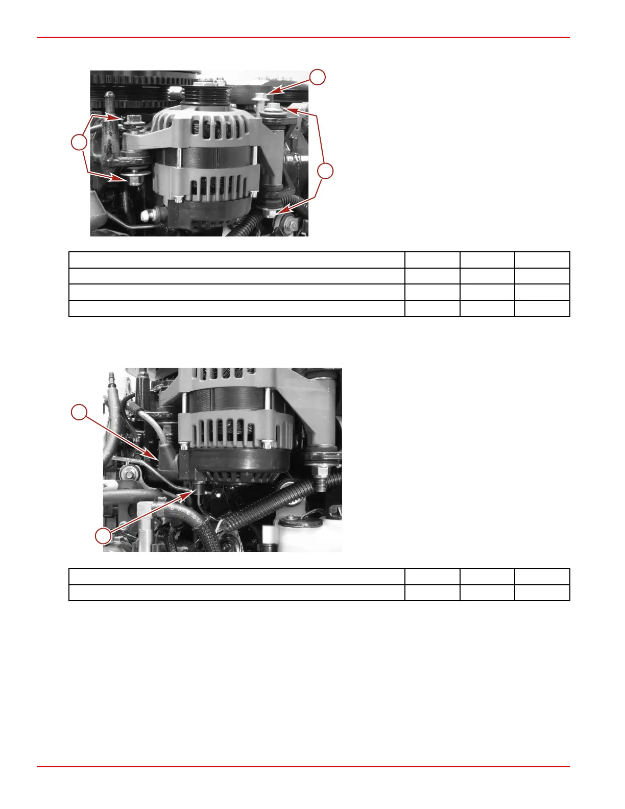
7. Tighten the M10 x 120 bolt and nut to the specified torque.
a - Bolt (M10 x 100)
b - Bolt (M10 x 55) and nut
c - Bolt (M10 x 120) and nut
Description Nm lb‑in. lb‑ft
Bolt (M10 x 100) 75 55
Bolt (M10 x 55) and nut 54 40
Bolt (M10 x 120) and nut 54 40
8. Connect the excitation/sensing wire connector to the alternator.
9. Connect the fusible link cable to the alternator output terminal. Secure the fusible link cable with a M6 nut. Tighten the nut to
the specified torque. Protect the alternator output terminal with the insulator boot.
a - Fusible link cable
b - Excitation/sensing wire connector
Description Nm lb‑in. lb‑ft
Nut (M6) 7 62

 Loading...


