Powerhead
Page 4A-60 90-8M0050731 MAY 2011
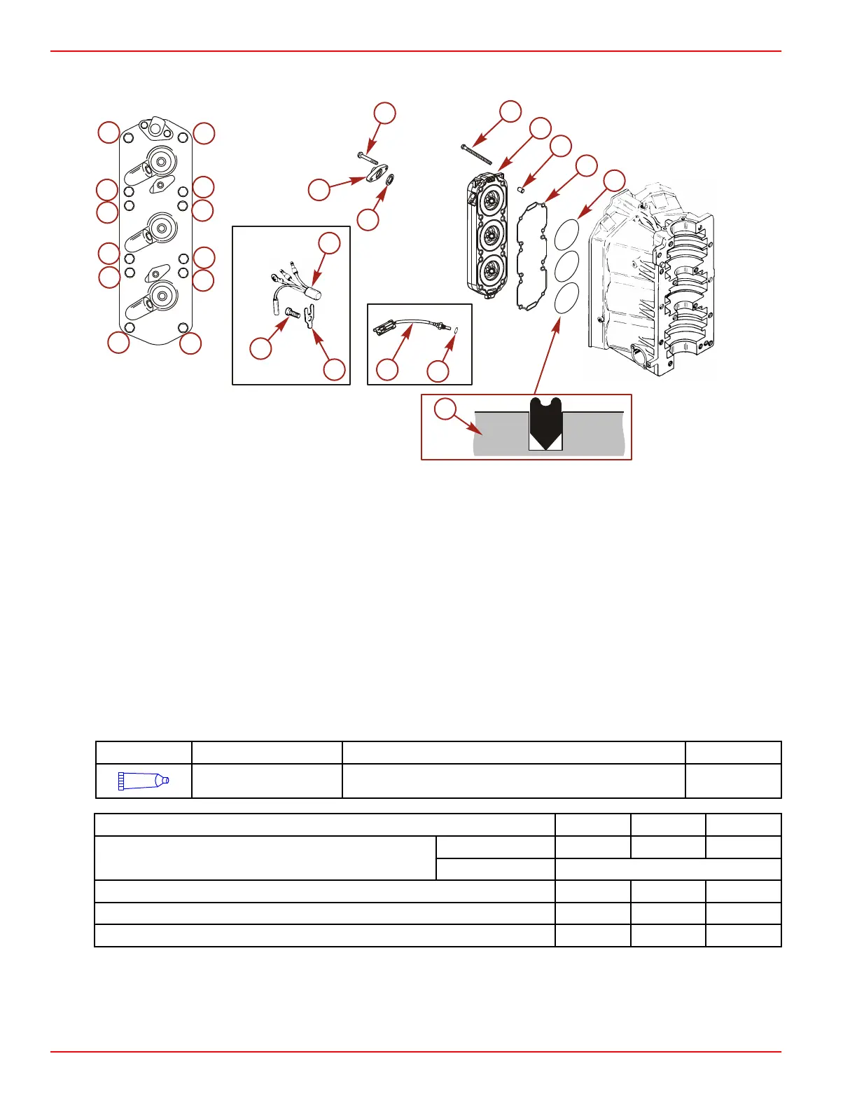
6. Install the cylinder heads onto the cylinder block. Tighten the cylinder head screws in two stages, in sequence, to the specified
torque.
a - Cylinder head screw (12)
b - Cylinder head
c - Dowel pin
d - Seal
e - Seal
f - Retainer
g - Screw (M8 x 12)
h - Temperature sensor (S/N 0T178499 and below)
i - Temperature sensor (S/N 0T178500 and above)
j - O‑ring
k - Gasket
l - Cover
m - Screw (M6 x 25) (2)
n - Cylinder head seal direction
Tube Ref No. Description Where Used Part No.
14
2-cycle Premium
Outboard Oil
Cylinder head screw threads and face 92-858021K01
Description Nm lb‑in. lb‑ft
Cylinder head screw
First
40.5 30
Final
Turn additional 90°
Screw (M8 x 12) 23 203 17
Screw (6M x 25) 23 203 17
Temperature sensor 17 150 12

 Loading...


