Pump Unit
Page 5A-22 90-8M0050731 MAY 2011
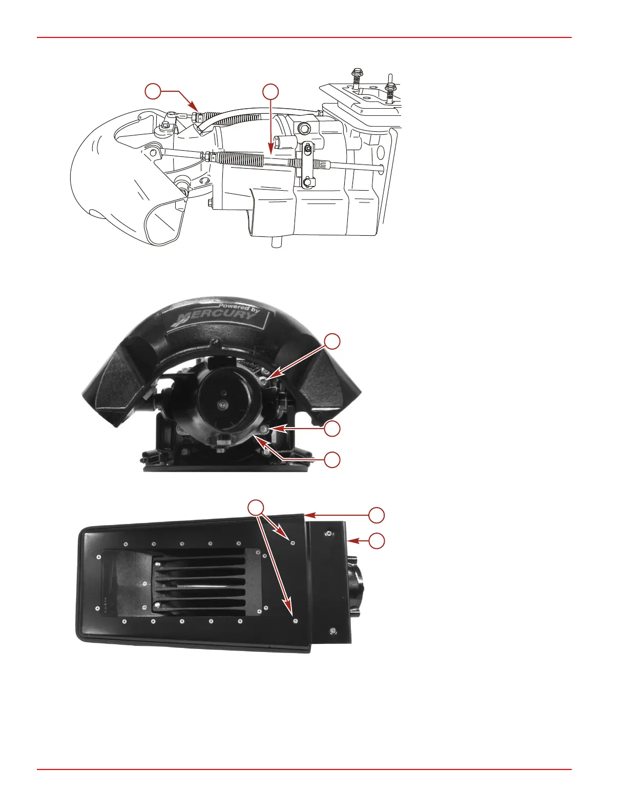
2. Disconnect shift and steering cables at reverse gate and rudder.
a - Shift cable
b - Steering cable
IMPORTANT: This procedure lists the disassembly of external pump components. If servicing a specific component, follow
the procedure in that section.
3. Remove four screws securing nozzle to stator. Remove the reverse gate/rudder/nozzle assembly.
a - Screw (M10 x 35, flange) (2)
b - Screw (M10 x 45, flange) (2)
c - Anode
4. Remove two screws securing the trim plate to the ride plate and wear ring.
a - Screws (M6 x 20) (2) (30 Torx)
b - Ride plate
c - Trim plate
5. Remove the fill/drain plug and allow the lubricant to drain into a suitable container. Install the fill/drain plug.
6. Remove four screws securing the stator assembly to the drive housing.

 Loading...


