Pump Unit
Page 5A-38 90-8M0050731 MAY 2011
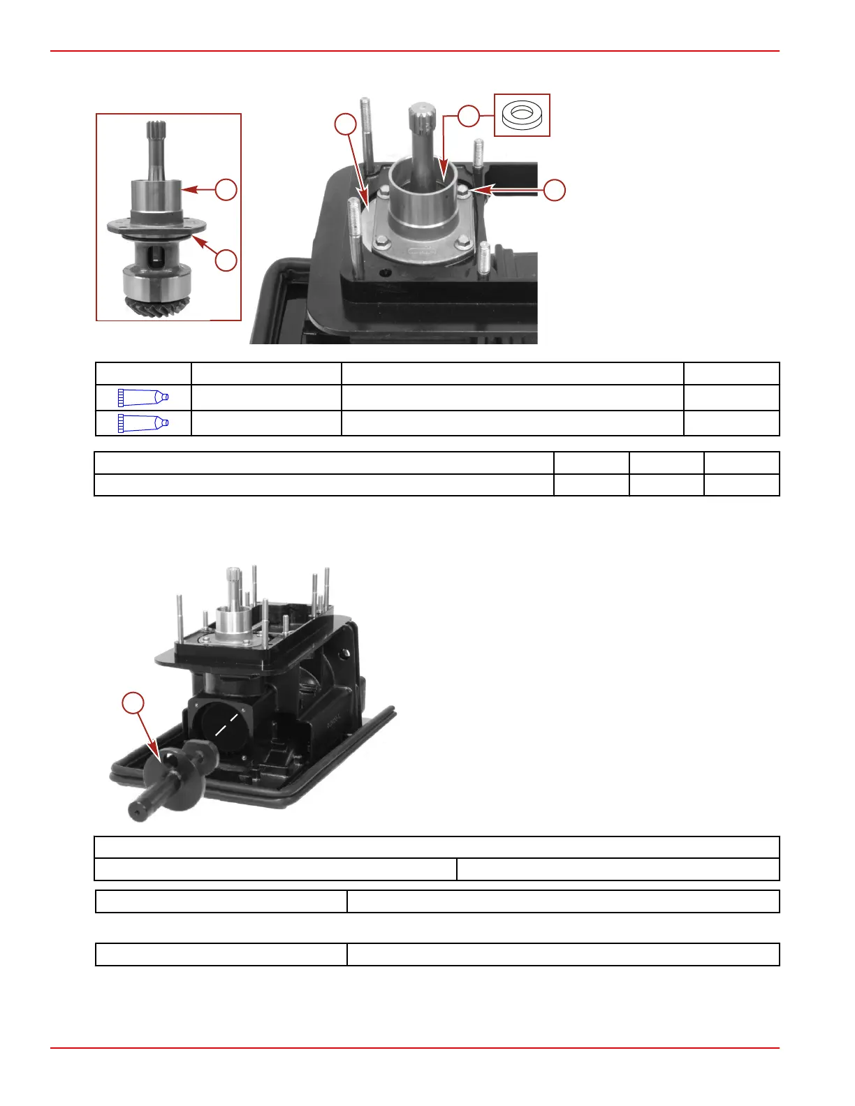
5. Install the rubber ring onto the pinion shaft until it lightly touches the shaft seal.
a - Pinion assembly
b - O‑ring
c - Shims
d - Screw (M8 x 25) (4)
e - Rubber ring
Tube Ref No. Description Where Used Part No.
95
2-4-C with Teflon Pinion shaft housing O-ring 92-802859A 1
7
Loctite 271 Threadlocker Pinion shaft housing screw threads (M8 x 25) 92-809819
Description Nm lb‑in. lb‑ft
Pinion shaft housing screws (M8 x 25) 20.5 181
6. Rotate the pinion shaft ten revolutions to properly seat the roller bearings.
7. Insert the pinion location tool into the drive housing.
NOTE: Carefully inspect the location tool to ensure it is seated in the drive housing bearing.
a - Pinion location tool
Pinion gear
Backlash specification 0.64 mm (0.025 in.)
Pinion Gear Height Location Tool 91‑831897
NOTE: 250 hp models, 1.15 gear ratio, use pinion height location tool 91‑882758.
Pinion Gear Height Location Tool
91‑882758
8. Insert the feeler gauge through the hole in the pinion location tool between the gauging surface of the tool and flats on the
bottom of the pinion gear teeth.
9. Use the 0.64 mm (0.025 in.) feeler gauge as a starting thickness. Adjust the thickness of the feeler gauge until a slight drag
is felt as the gauge is drawn out between the gauging surface of the tool and the pinion gear.

 Loading...