Pump Unit
Page 5A-40 90-8M0050731 MAY 2011
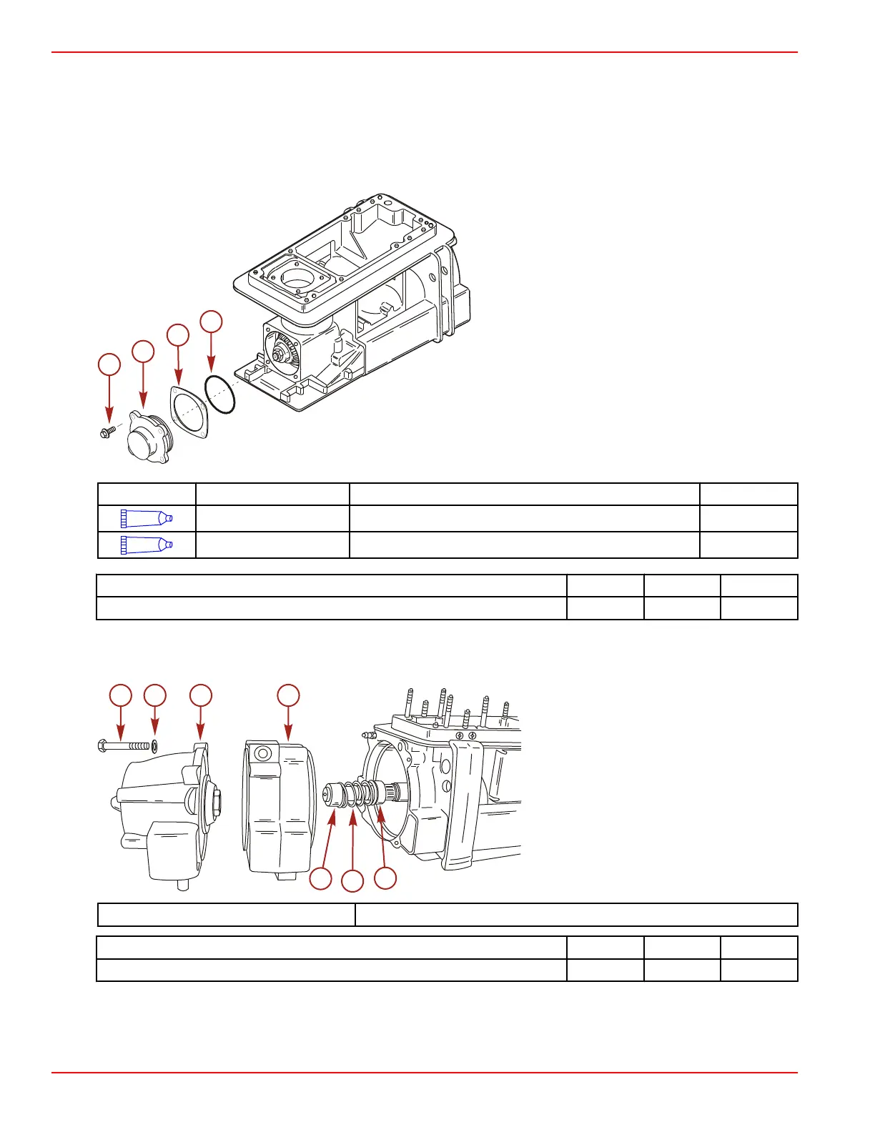
4. Install the original shims onto the impeller shaft cover. Install the O‑ring on the impeller shaft cover.
NOTE: If the original shims are not available, start with 0.76 mm (0.030 in.) shims.
• Lubricate the O‑ring and bore with 2‑4‑C with Teflon.
• Lubricate the cone bearing with gearcase lubricant.
5. Install the impeller shaft cover.
6. Apply Loctite 271 Threadlocker to the screw threads. Tighten the screws to the specified torque.
a - Screw
b - Cover
c - Shim
d - O‑ring
Tube Ref No. Description Where Used Part No.
95
2-4-C with Teflon Impeller shaft bore and O-ring 92-802859A 1
7
Loctite 271 Threadlocker Pinion shaft housing screws (M8 x 25) 92-809819
Description Nm lb‑in. lb‑ft
Impeller shaft cover screws (M8 x 25) (4) 20.5 181
7. Install the impeller shaft preload tool.
8. Install the wear ring and stator onto the impeller shaft. Secure the assembly with two bolts (opposite corners). Tighten the
bolts to the specified torque.
a - Bolt (M10 x 150)
b - Washer
c - Stator
d - Wear ring
e - Rear spring seat
f - Spring
g - Forward spring seat
Impeller Shaft Preload Kit 91‑824871A 1
Description Nm lb‑in. lb‑ft
Wear ring/stator bolts (M10 x 150) 47 35
9. Rotate the impeller shaft ten revolutions to properly seat the roller bearings.
10. Install the backlash indicator rod onto the pinion shaft.
11. Install the dial indicator kit, adapter kit, and thread extending kit.

 Loading...