Pump Unit
Page 5A-42 90-8M0050731 MAY 2011
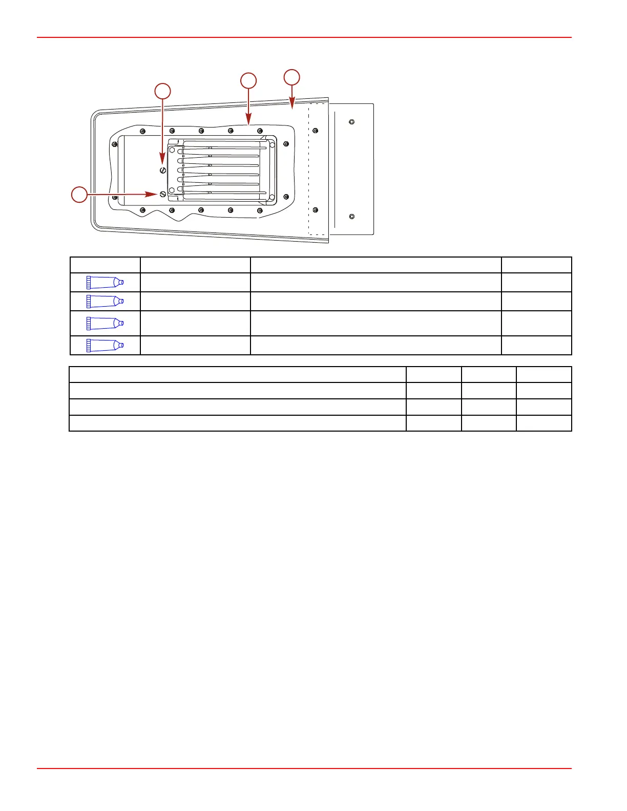
IMPORTANT: The pump housing must be level and upright to obtain the correct fluid level.
Bottom view
a - Ride plate
b - Loctite 598 RTV Sealant
c - Vent screw
d - Drain/fill screw
Tube Ref No. Description Where Used Part No.
7
Loctite 271 Threadlocker Nozzle/reverse gate assembly and anode bolt threads 92-809819
66
Loctite 242 Threadlocker Ride plate bolt threads (M6 x 20) (16) 92-809821
87
High Performance Gear
Lubricant
Stator and drive housing 92-858064K01
142
Loctite 598 RTV Sealant Ride plate Obtain Locally
Description Nm lb‑in. lb‑ft
Ride plate bolts (M6 x 20) (16) 8.5 75
Nozzle bolts (M10 x 35) (2) 47 35
Anode bolts (M10 x 45) (2) 47 35
5. Install the drive housing, shift, and steering cables. Refer to Section 1D - Mercury Jet Installation.

 Loading...