098-00720-000 Revision D1 – February, 2018 SyncServer 600 Series User’s Guide 303
Appendix C Installing GNSS Antennas
Antenna Kits Overview
Lightning does not have to strike the antenna to significantly damage the antenna or
the GNSS receiver. Damage is often due to the effects of a lightning strike on a
nearby structure, not a direct strike on the antenna itself. Since lightning strikes may
induce damaging voltages in the antenna system when striking nearby objects,
attempt to locate the antenna away from lightning rods, towers, and other structures
that attract lightning. Also, locate the GNSS antenna lower than any nearby
structures that are likely to attract a strike. See Figure C-2.
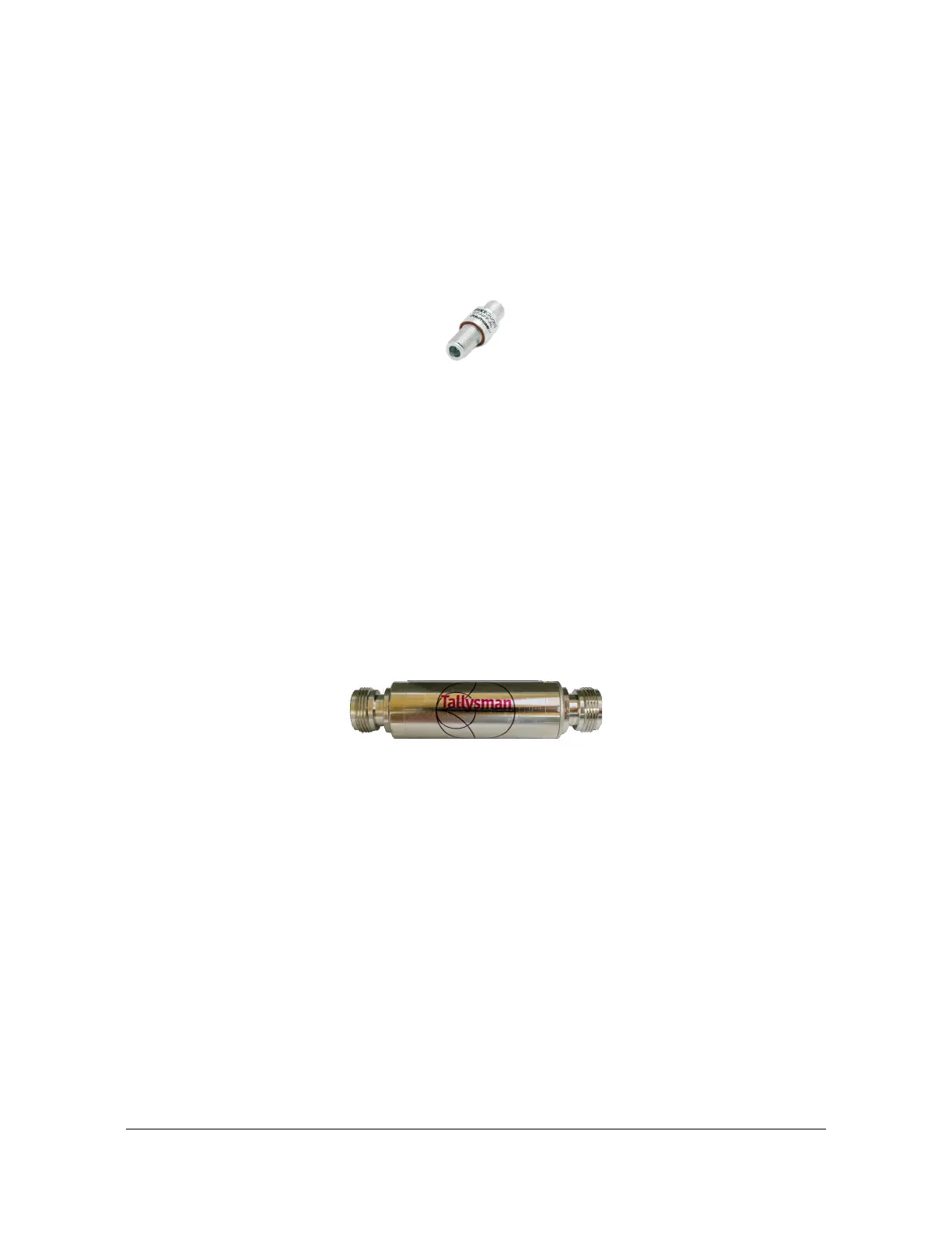
Figure C-2. GNSS Lightning Arrestor
GNSS L1 In-line Amplifier
The GNSS L1 in-line amplifier (093-15202-005) option boosts the signal from the
antenna with total cable lengths of 150 and 230 meters. See the GNSS L1 Inline
Amplifier Specifications, on page 286 for specifications.
Cable length is a common cause for signal loss between the GNSS antenna and the
GNSS receiver. As with any electromagnetic radio wave, GNSS signals become
attenuated as they pass through an electrical cable. The amount of signal loss
depends on the length and type of cable used. The inline amplifier attaches inline
between the antenna and the antenna cable. It uses the same power as the
antenna and does not require extra wiring. The inline amplifier supports a total cable
length up to 900 feet depending on the cable type. See Figure C-3.
Figure C-3. Inline Amplifier
GPS L1 1:4 Active Splitter
The active splitter features four output ports, as shown in Figure C-4. See the GPS
L1 1:4 Active Splitter Specifications, on page 287 for specifications.This high
isolation device can be cascaded without adding separate amplifiers and bias-tees
between splitters. The splitter delivers precise GPS signals over a wide temperature
range and in harsh environmental conditions. It eliminates feedback and interaction
between any GPS system connected to it.