098-00720-000 Revision D1 – February, 2018 SyncServer 600 Series User’s Guide 59
Chapter 2 Installing
Signal Connections
Timing I/O Module Connections
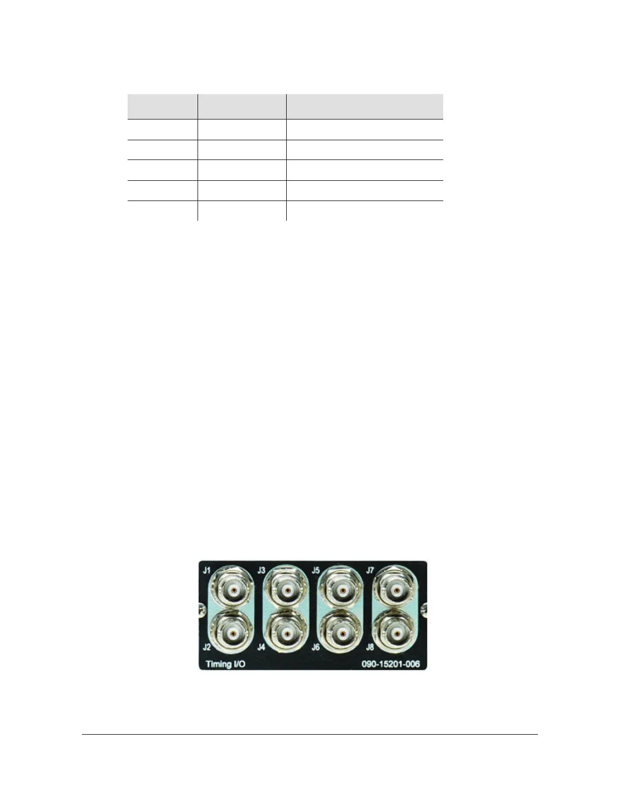
The standard configuration offers a broad yet fixed selection of signal I/O on its eight
BNC connectors (see Figure 1-26). J1 is dedicated to time code and rate inputs, J2
to sine wave inputs, and J3-J8 to mixed signal outputs. The standard Timing I/O
Module configuration is 1PPS or IRIG B AM-In, 10 MHz- In, IRIG AM and IRIG
DCLS-Out, 1PPS-Out and 10 MHz-Out.
The FlexPort™ Technology option enables the 6 output BNCs (J3-J8) to output any
supported signal (time codes, sine waves, programmable rates, and so on.) on all
configurable in real time via the secure web interface. Similarly, the 2 input BNCs
(J1-J2) can support a wide variety of input signal types. This uniquely flexible BNC
by BNC configuration makes very efficient and cost effective use of the 1U space
available.
See Figure 1-27 to view the signal types for the standard configuration and the
configuration with the FlexPort™ option. See Figure 2-14.
Figure 2-14. Timing I/O BNC Connections
Cisco single mode SFP-10G-LR
Juniper multi-mode SFPP-10G-SR
Juniper single mode SFPP-10G-LR
Juniper multi-mode EX-SFP-10G-SR
Juniper single mode EX-SFP-10G-LR
Table 2-3. Recommended and Supported SFP+ (10GbE) Transceivers
Vendor
Mode Item Code or P/N