42 SyncServer 600 Series User’s Guide 098-00720-000 Revision D1 – February, 2018
Chapter 1 Overview
Functional Description
LEDs
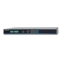
The SyncServer S6x0 provides three LEDs on the front panel, as shown in Figure
1-33, that indicate the following:
Sync Status
Network Status
Alarm Status
Figure 1-33. LEDs for SyncServer S3x0
See Figure 2-6 for details about the LEDs.
Communication Ports
Communication ports on the SyncServer S6x0 allow you to provision, monitor, and
troubleshoot the chassis with CLI commands.
Management Ethernet Port
The system web interface for full control is located on Ethernet port 1 (LAN1) and is
used as the Management Ethernet connector to provide connectivity to an Ethernet
local area network. The front panel can be used to configure an IPv4 address (static
or DHCP) or enable DHCP for IPv6. Once the IP address is set and a connection is
made to a Local Area Network (LAN), you can access the SyncServer S6x0 web
interface.
Local Console Serial Port
The serial port supports very limited local control; you can configure the SyncServer
S6x0 with CLI commands using a terminal or computer with terminal emulation
software. The connector is located on the front panel. The Local port is configured
as a DCE interface and the default settings are as follows:
Baud = 115.2K
Data Bits = 8 bits
Parity = None
Stop bits = 1
Flow Control = None