52 SyncServer 600 Series User’s Guide 098-00720-000 Revision D1 – February, 2018
Chapter 2 Installing
Making Ground and Power Connections
Making Ground and Power Connections
The SyncServer S6x0 has either one or two 120/240 VAC connectors, depending
on the specific model, which are located on the left side of the rear panel. (see
Figure 2-4 and Figure 2-5).
Ground Connections
The frame ground connection is made using the grounding screw, which is marked
with the universal ground symbol, as shown in Figure 2-6. This screw is located on
the left side of the rear panel for all models of the SyncServer S6x0, as shown in
Figure 2-4 and Figure 2-5.
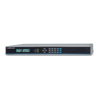
Figure 2-4. SyncServer S600/S650 Power & Ground Connections - Single AC Version
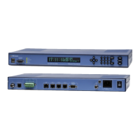
Figure 2-5. SyncServer S600/S650 Power & Ground Connections - Dual AC Version
Figure 2-6. Universal Ground Symbol
After installing the SyncServer S6x0 into the rack, connect the chassis to the proper
grounding zone or master ground bar per local building codes for grounding.