098-00720-000 Revision D1 – February, 2018 SyncServer 600 Series User’s Guide 57
Chapter 2 Installing
Signal Connections
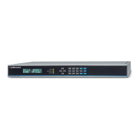
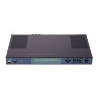
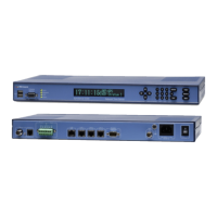
SyncServer S6x0 Synchronization and Timing Connections
The SyncServer S6x0 has one GNSS input and four NTP input/output connections.
The SyncServer S6x0 has one 1PPS output. The SyncServer S650 may also have
an optional Timing I/O Module.
GNSS Connection
To connect a GNSS signal to the SyncServer S6x0, you must install a GPS
antenna. See Connecting the GNSS Antenna, on page 61.
Ethernet Connections
The Ethernet ports are standard 100/1000 Base-T shielded RJ-45 receptacles,
which are used for NTP inputs. To connect the SyncServer S6x0 to an Ethernet
network, use an Ethernet RJ-45 cable. See Table 2-2 for connector pinouts.
Caution: The GNSS cable should only be connected while the unit is
properly earth grounded.
Warning: To avoid possible damage to equipment, you must provide
external lightning protection when installing the GNSS antenna to
prevent transients.
Table 2-2. System Management Ethernet Connector Pin Assignments
RJ-45 Pin
100Base-T Signal 1000Base-T Signal
1 TX+ (Transmit positive) BI_DA+
2 TX- (Transmit negative) BI_DA
3 RX+ (Receive positive) BI_DB+
4 Not Used BI_DC+
5 Not Used BI_DC
6 RX- (Receive negative) BI_DB
7 Not Used BI_DD+
8 Not Used BI_DD