CONFIGURATION AND FUNCTION
1-7
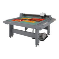
Right-hand side face of the electrical box
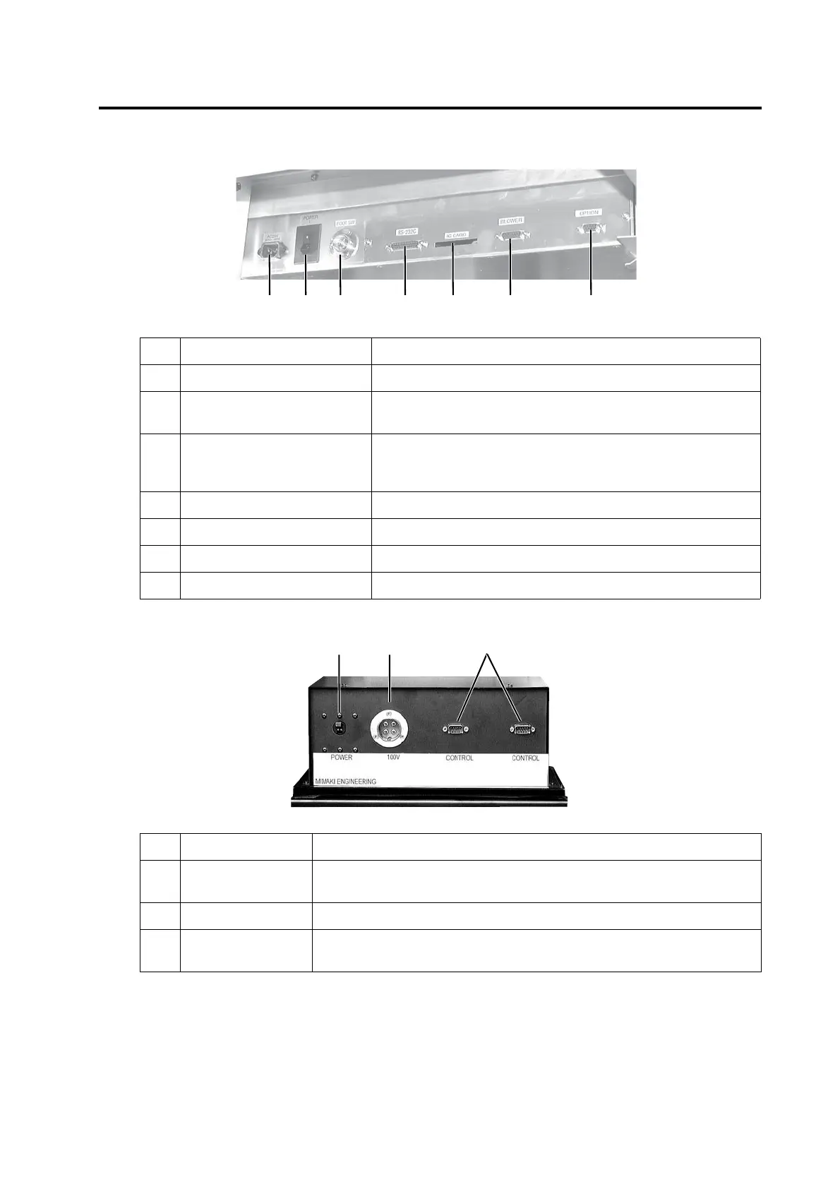
Blower unit (Option)
Name Function
1 Power connector To be connected to the power cable of the plotter.
2 Main power switch Used to turn on/off the main power of this device. Normally set it to the
on state. Set it to the off state when conducting maintenance works.
3 Foot switch connector Foot switch for vacuum is connected to this connector. (Optional)
Note: The shape of this connector may differ from that shown in the pho-
tograph.
4 RS-232C interface To be connected to a personal computer using an interface cable.
5 IC card slot To be used when conducting maintenance works.
6 Signal wire connector for blower To be connected to the blower unit (option) using a signal wire.
7 Optional connector Connector to support particular purpose use.
Name Function
1 Power switch Used to turn on/off the power to the blower unit. Normally, it is set to the
on position. Turn it off when conducting maintenance works.
2 Power connector The power cable for the blower is connected to this connector.
3 Signal wire connector To be connected, using a signal wire, to the signal wire connector for the
blower on the electrical box.
 Loading...


