1-22
Setting the command origin [MODE SET] > [ORIGIN]
Adjust the position of the command origin of the device to the origin of the command origin of your CAD. Refer to
the Operation manual for your CAD for the position of the command origin supported by the CAD.
Set values
LOWER LEFT: The command origin is set to the lower left of the maximum effective cutting area.
CENTER: The command origin is set to the center of the maximum effective cutting area.
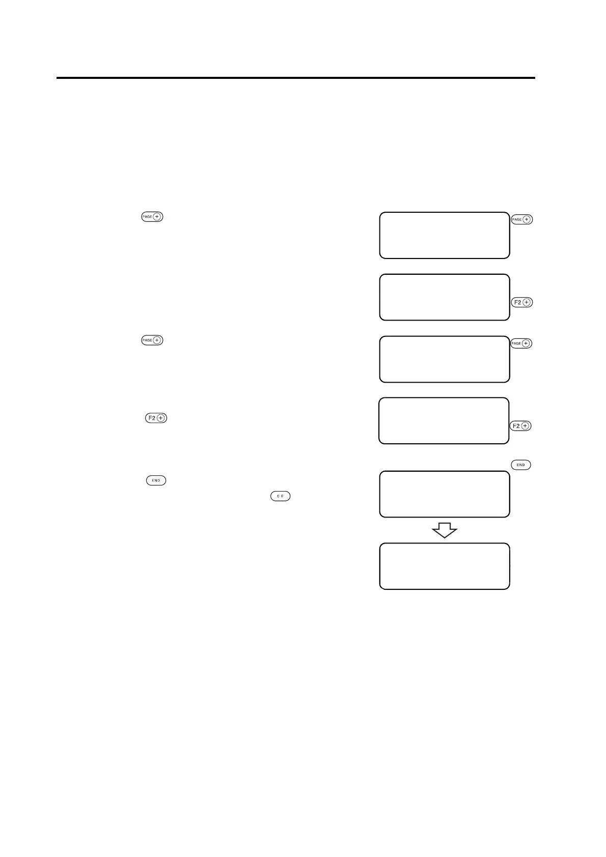
1. Press the key several times until the LCD indicates
page 3 of the LOCAL MENU.
2. Select the [MODE SET].
3. Press the key several times until the LCD indicates
page 4 of the [MODE SET].
4. Set the [ORIGIN].
Press the key to change the selected item alternately.
LWR LEFT, CENTER
5. Enter the input values.
Press the key to enter the input values.
If you do not enter the input data, press the key.
[LOCAL] 1 / 4
TOOL SELECT ――― >
CONDITION ――― >
TEST CUT ――― >
[ LOCAL] 3 / 4
INTERFACE ――― >
MODE SET ――― >
SELF TEST ――― >
<MODE SET> 1/6
Z STROKE *7mm >
MULTI–PASS ――― >
VACUUM * AutoOFF >
<MODE SET> 4/6
OH UNIT ∗ INIT val >
ORIGIN ∗ CENTER >
G D P ∗ 0.025 mm >
<MODE SET> 4/6
OH UNIT ∗ INIT val >
ORIGIN ∗ LWR LEFT >
G D P ∗ 0.025 mm >
[LOCAL] 3 / 4
INTERFACE ――― >
MODE SET ――― >
SELF TEST ――― >
 Loading...


