SETTING CUTTING CONDITIONS [CONDITION]
2-27
Setting cutting conditions
The following describes how to establish cutting conditions for cutter 2 (tangential cutter) as an example.
Once you have set cutting conditions, execute the [TEST CUT] function to check whether or not the cutting condi-
tions are proper. ( P. 2-29)
1. Select the head and the tool in the [TOOL SELECT].( P. 2-22)
Select B for the head and cutter 2 for the tool.
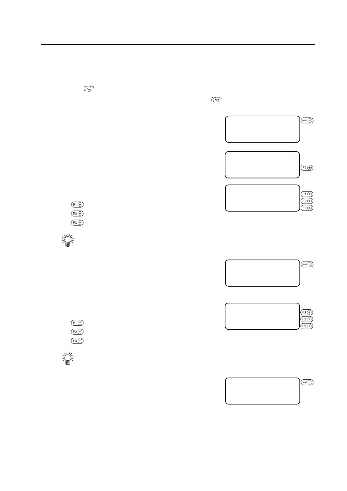
2. Invoke the 1st page of the LOCAL MENU.
3. Select the [CONDITION].
Select the CONDITION, and the cutting conditions for the cutter 2
will appear on the screen.
4. Set the speed, pressure and acceleration to adequate
values.
..... Input a speed.
..... Input a pressure.
..... Input an acceleration.
5. Invoke the 2nd page of the cutting conditions screen for
cutter 2.
6. Set the [START CORRECTION], [END CORREC-
TION] and [UP ANGLE] to adequate values.
..... Input a start correction.
..... Input an end correction.
..... Input an up angle.
7. Invoke the 3rd page of the CUTTING CONDITIONS
screen for cutter 2.
• If the “– (minus)” key of the respective function
keys is pressed, a previous value is indicated on
the display.
• If the “– (minus)” key of the respective function
keys is pressed, a previous value is indicated on
the display.
[LOCAL] 1 / 4
TOOL SELECT ――― >
CONDITION ――― >
TEST CUT ――― >
[LOCAL] 1 / 4
TOOL SELECT ――― >
CONDITION ――― >
TEST CUT ――― >
< CUTTER 2 > 1 / 4
SPEED * 2 0 c m / s >
PRESSURE * 4 0 0 g >
ACCELE * 0 . 2 G >
< CUTTER 2 > 1 / 4
SPEED 3 0 c m / s >
PRESSURE 9 0 0 g >
ACCELE 0 . 3 G >
< CUTTER 2 > 2 / 4
F OFFSET * 0 . 5 0 mm >
E OFFSET * 0 . 5 0 mm >
UP ANGLE * 3 0 ° >
< CUTTER 2 > 2 / 4
F OFFSET 1 . 0 0 mm >
E OFFSET 1 . 0 0 mm >
UP ANGLE 1 5 ° >
 Loading...


