1-6
CONFIGURATION AND FUNCTION
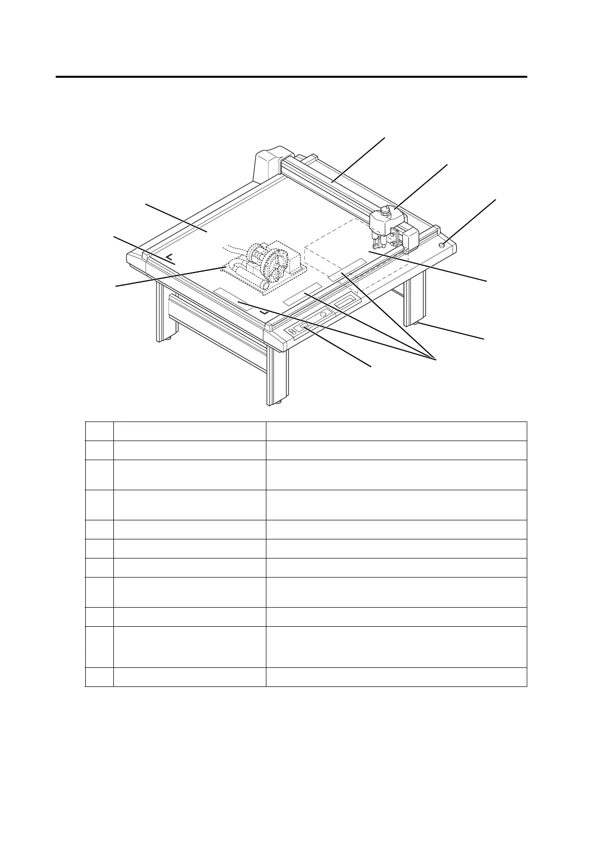
Main unit
Name Function
1 Y bar Moves the head in Y direction
2 Head Tools are attached to the head. Tools that can be set to the head dif-
fers with the models of heads.
3 EMERGENCY switch To be pressed at the time of emergency. Pressing this switch force-
fully turns the power off to make the device to stop performance.
4 Electrical box PCBs or the like are built in this box.
5 Adjuster foot Adjusts the height of foot and keeps the cut panel surface leveled.
6 Work guide Align the work to set straight.
7 Operation panel Data required for the operation of the device are specified on this
panel.
8 Blower unit (Option) This allows a work to be pneumatically picked on the cut panel.
9 Cut panel (felt mat) A board to which a work is attached. Air-suction small holes are
arranged regularly on it. When using a reciprocal cutter, place it on
this felt mat.
10 Origin marker label Indicates the maximum effective cutting area.
 Loading...


