4-2
ASSIGNMENT OF PEN NUMBERS [MODE SET] > [PEN ASIGN]
Pen numbers included in data are assigned to tools of the device. As many as six pens can be assigned to the tools.
Operating procedure is described in this section using the example given below.
Pen 1 (Pen number in data to be plotted) → Pen
Pen 2 (Pen number in data to be cut) → Cutter 2
If the pen numbers are assigned as stated above, data on pen 1 and pen 2 an be plotted and cut at a time.
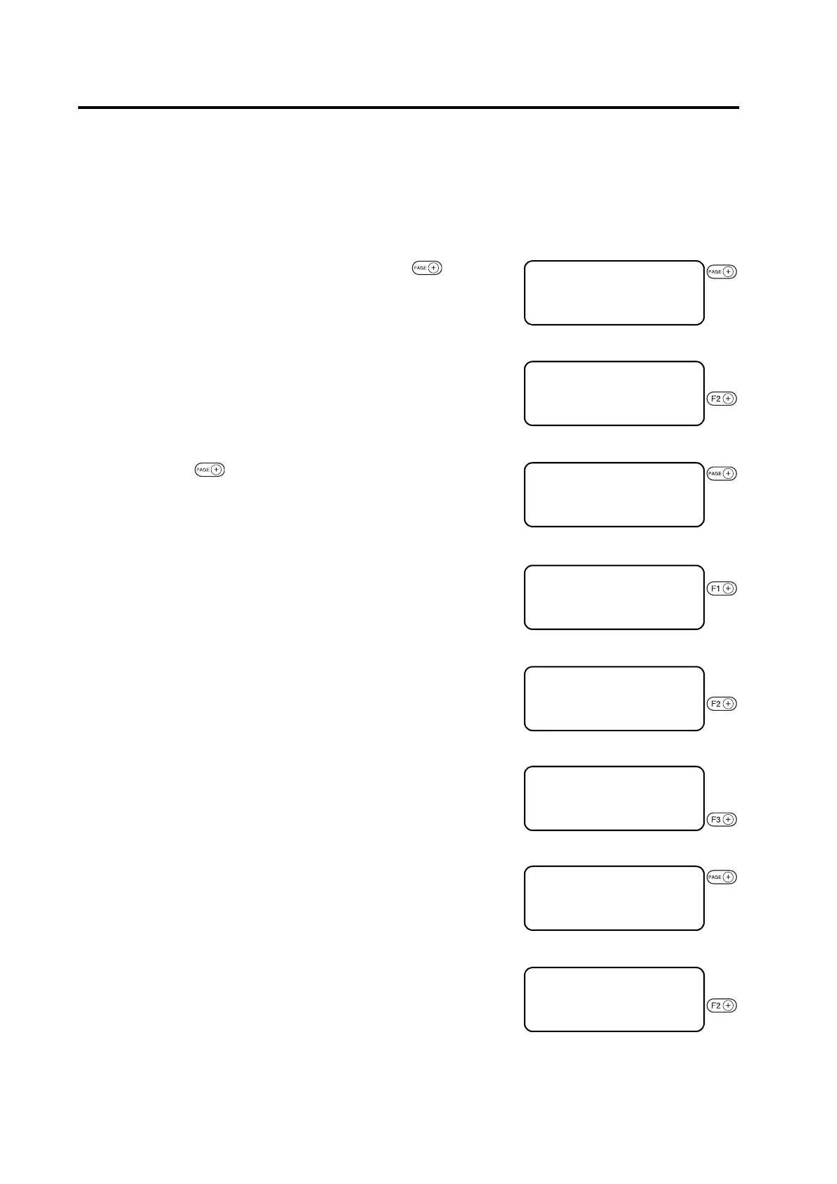
1. Invoke the LOCAL menu on the Press the key sev-
eral times until the LCD indicates page 3 of the LOCAL
MENU.
2. Select the [MODE SET].
3. Press the key several times until the LCD indicates
page 5 of the [MODE SET].
4. Select the [PEN ASIGN].
5. Change the head from [B] to [A].
B, A
6. Set the tool to [PEN].
Pen, Swivel blade
7. Invoke the [PEN 2] setting menu.
8. Change the head from [A] to [B].
A, B
[LOCAL] 1 / 4
TOOL SELECT ――― >
CONDITION ――― >
TEST CUT ――― >
[LOCAL] 3 / 4
INTERFACE ――― >
MODE SET ――― >
SELF TEST ――― >
< MODE SET > 1 / 6
Z STROKE * 7 mm >
MULTI–PASS ――― >
RESERVE
< MODE SET > 5 / 6
PEN ASIGN ――― >
RESERVE
UNIT * mm >
< PEN ASIGN > 1 / 6
PEN 1
HEAD * B >
TOOL ∗ RecCutter 1 >
< PEN ASIGN > 1 / 6
PEN 1
HEAD A >
TOOL *ペン>
< PEN ASIGN > 1 / 6
PEN 1
HEAD A >
TOOL *ペン>
< PEN ASIGN > 2 / 6
PEN 2
HEAD * A >
TOOL ∗ RecCutter 1 >
 Loading...


