1-11
CONNECTING THE CABLES
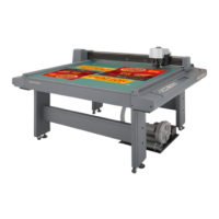
Connecting the signal wire cable for the blower
The signal wire cable for the blower connect the electrical box located below the cutting panel surface to the blower
unit.
1. Insert one end of the signal wire cable for the
blower into the connector of the electrical box.
Fix the connector with screws.
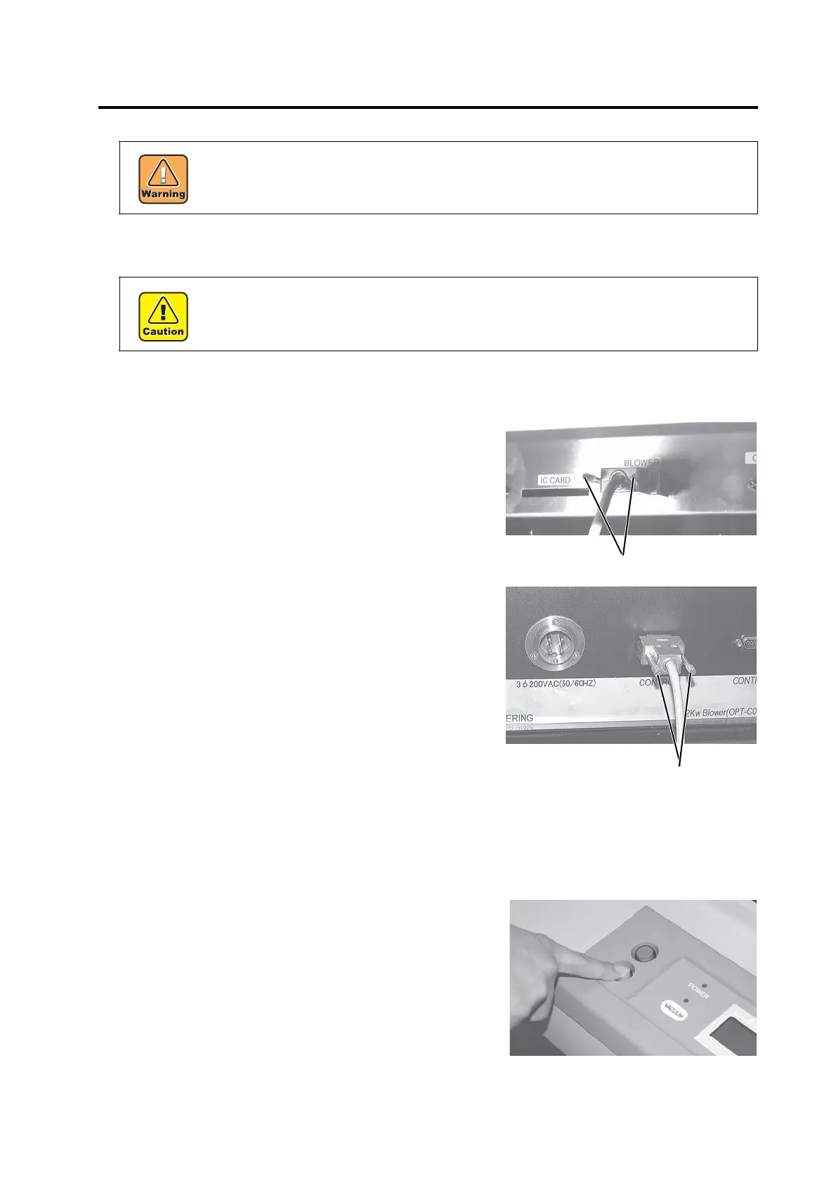
2. Insert the other end of the signal wire cable for the
blower into the connector on the blower unit
(option).
Fix the connector with screws.
Connecting the interface cable
The device is equipped as standard with an interface conforming to RS-232C.
Use a MIMAKI-recommended interface cable or a cable that matches your computer.
1. Turn off the power to the plotter and that to the
personal computer.
• Be sure to turn off the the power to the device in prior when connecting the signal wire cable
for the blower, interface cable. If not, there will be a fear of the arising of electric shock haz-
ards and damage to the device.
• Do not block the exhaust port of the blower unit (option). Blocking it can drop the suction
force or give rise to a failure.
 Loading...


