EasyManuals Logo

Minebea Intec X3 Process Indicator PR 5410 User Manual

Minebea Intec X3 Process Indicator PR 5410
340 pages
To Next Page IconTo Next Page
To Previous Page IconTo Previous Page
Page #50 background imageLoading...
Page #50 background image
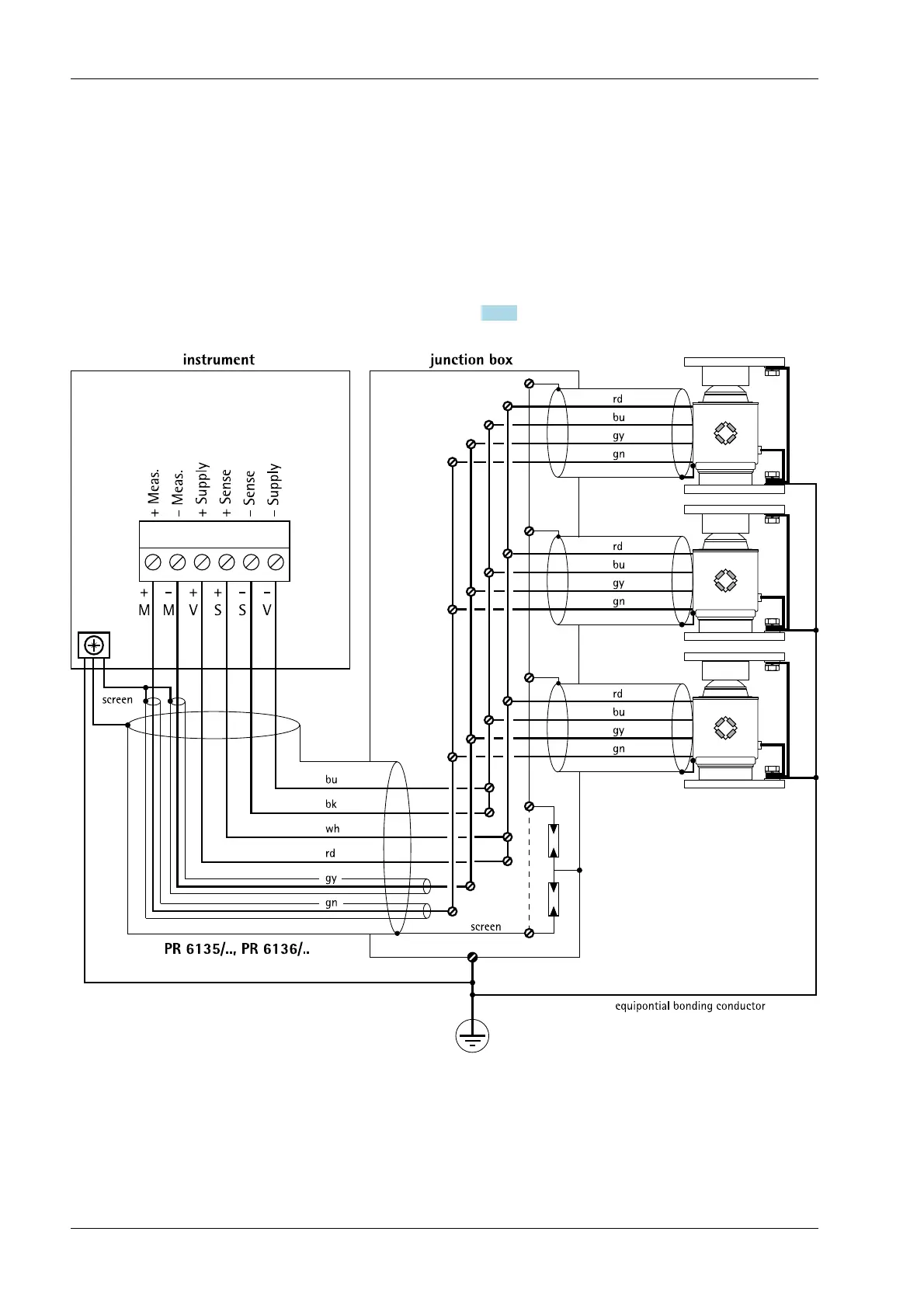
4.5.4 Connecting between 2 and8 load cells (650 ) using a 6-wire connection cable
Connections are made via cable junction box PR 6130/.. using connection cable PR 6135/..
or PR 6136/... .
Load cell supply circuit
- Load resistance of load cell circuit ≥75 , e.g., 8 load cells of 650 each
- The supply voltage is xed at 12 V DC and protected against short circuits.
For further technical data, see Chapter 17.5.1.
4.5.5 Connecting load cells of type series PR 6221
See installation manuals of PR 6221 and PR 6021/08, -/68.
X3 Process Indicator PR 5410 4 Device installation
Minebea Intec EN-48

Table of Contents

Questions and Answers:

Question and Answer IconNeed help?

Do you have a question about the Minebea Intec X3 Process Indicator PR 5410 and is the answer not in the manual?

Minebea Intec X3 Process Indicator PR 5410 Specifications

General IconGeneral
BrandMinebea Intec
ModelX3 Process Indicator PR 5410
CategoryTouch Panel
LanguageEnglish