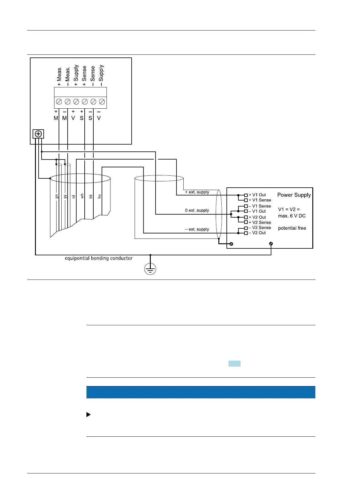
4.5.8 Connecting to input/output interface PR 1626/60
Connections are made via connecting cable PR 6135/.. .
The internal load cell supply voltage (V+, V-) of the PR 5410 must not be connected.
Note:
For additional connections, refer to the PR 1626/60 instrument manual.
If the solder bridge MX8 in the PR 1626/60 is closed (7.5 V DC), the solder bridge (12) on
the PR 5410 main board must be opened (see Chapter 4.4.1). The sense voltage
detection is now switched.
NOTICE
Installation in explosion-hazarded areas
The screen of the load cell cable and the screen of the connecting cable must not be
connected inside the junction box whenever regulations governing installation in
explosion-hazarded areas prohibit any connection of the two ends.
X3 Process Indicator PR 5410 4 Device installation
Minebea Intec EN-50