118 MI-42-0001 Rev. 19
SCANNING: Typical Scan Sequence: New Scan
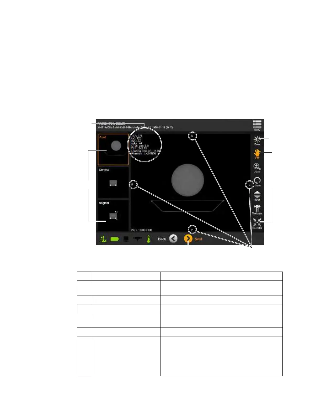
6.8.19 Summary of 3D Image Controls
Overview The system displays the reconstructed CT scan data in the DICOM Viewer for evaluating the image.
The viewer:
• Orients the image based on the scan direction.
• Tags the image with DICOM markers for Head, Foot, Left, Right, Anterior and Posterior (H, F, L,
R, A, P) ends of anatomical axes defined by the selected patient orientation. See 6.8.9
Selecting Patient Orientation and Position.
• Provides a variety of viewing controls.
NOTE: The DICOM Viewer is used only for evaluating the image. Use an external diagnostic
viewing device that meets local regulatory requirements when examining images for diagnostic
purposes.
Figure 91
No. Component Function/Usage
a
Thumbnails of main Image
View
Changes main image orientation to selection.
s
Window/Level Optimizes image for tissue level selected.
d
Image Tools Manipulate image.
f
Next
Send scan to DICOM or USB storage device. See
section 6.8.24 Sending Scan to DICOM or USB.
g
Axes-end markers Show ends of anatomical axes on the 3D image
h
3D Position, kV, mA, mAs,
Dosage, and Image metrics
Shows metrics for position in 3D image, and scan
values for kV, mA, mAs, CTDI
vol
, DLP, scan load time,
and reference phantom.
For helical scans with Modulated Tube Current, the mA
and mAs values are scan averages, with current slice
values also shown. See Figure 95.