MI-42-0001 Rev. 19 223
TECHNICAL DESCRIPTION: Symbols
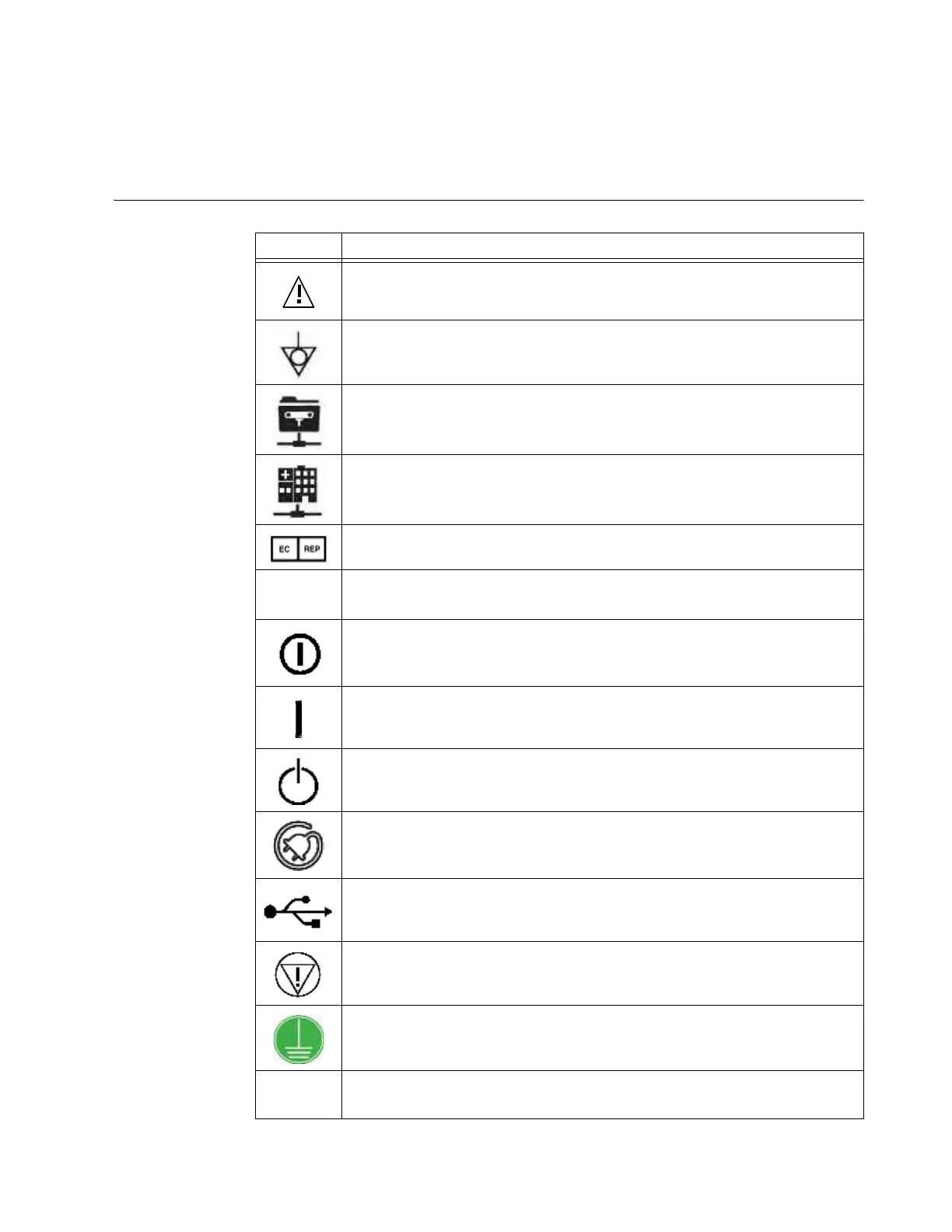
9.14 Symbols
9.14.1 Symbols Used
Symbols and
Explanations
Symbol Explanation
Warning. Consu
lt the accompanying documents for important safety-related
information such as warnings and precautions that cannot, for a variety of
reasons, be presented on the device itself.
Potential equalization point
Ethernet port for communication with the image guidance system software from
your navigation system vendor.
Ethernet port for communication with the hospital network.
Authorized representative in the European Community
IPXY
X = Protection against ingress of solid objects
Y = Protection against ingress of liquid
On/off push switch
When pressed
On
, a yellow indicator light next to the switch indicates that the
system is powered on.
Power On key switch position for enabling the On/Off push switch
Standby key switch position for shutting down the system software and putting the
device into standby mode
AC power connection indicator
When the indicator light is lit, the AIRO is plugged in and charging Ring batteries.
USB connection for exporting data
Emergency Stop
Available on Pendant (see Figure 163 on page 228)
Protective Earth Terminal
CAUTION: Federal law restricts this device to sale by or on the order of a
physician