240 MI-42-0001 Rev. 19
CT USER INFORMATION: Dosage Factors and Image Quality
10.3.3 Statement of Maximum Deviations
Maximum
Deviations
Unless specified, no value should exceed the allowable deviation of ± 10% (suggested). For CTDI
w
,
CTDI
vol
and DLP,
measured values should not differ from displayed values by ± 30%.
NOTE: The 30%
allowable error is suggested because most physicists routinely measure entrance
CTDI
100
at the 12 o’clock position, which can be higher than CTDI
100
(peripheral)
by >25%. Medical
Physics testing for ACR accreditation also employs measurement at the 12 o’clock
position.
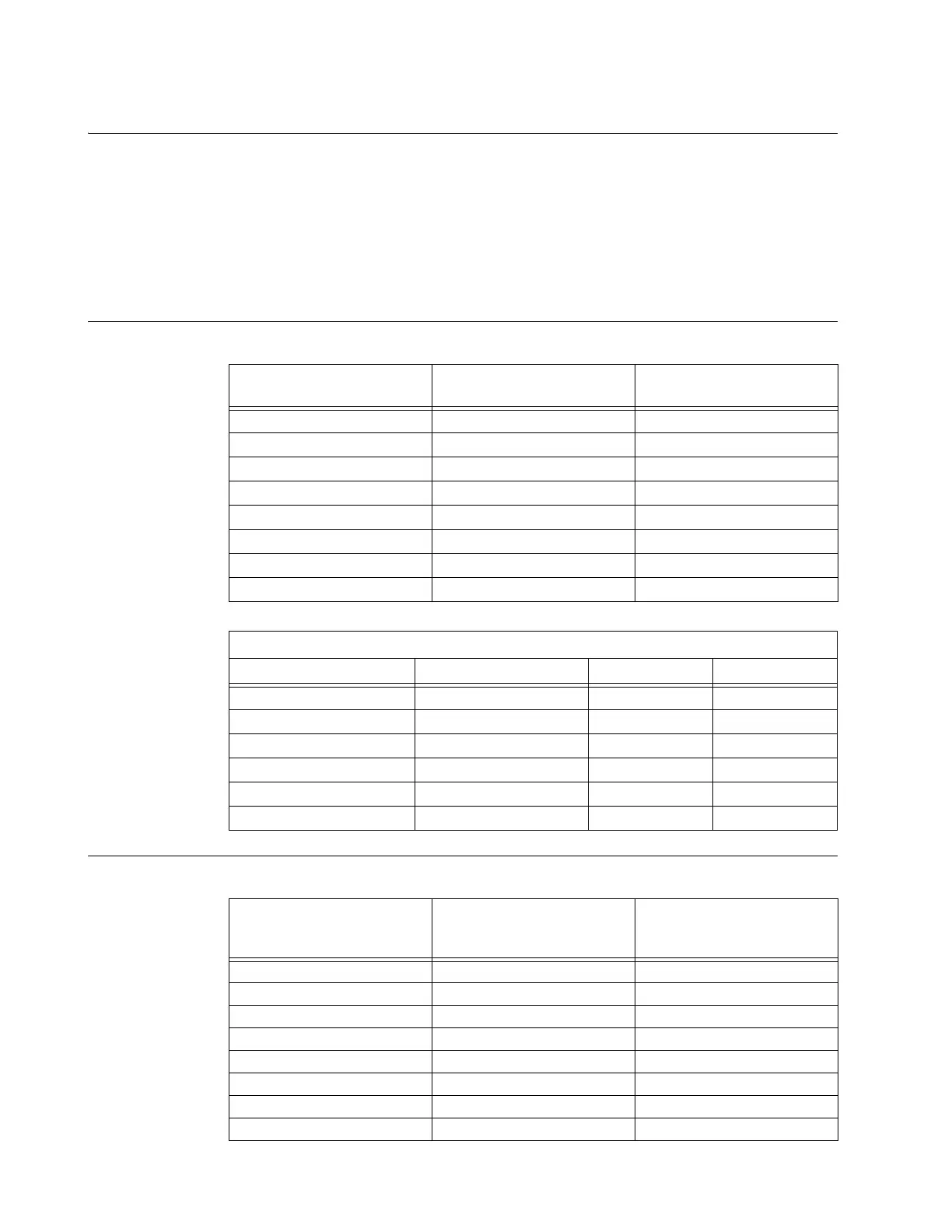
10.3.4 Imaging Performance Information
Noise, Mean CT
Number, and
Uniformity – Head
Scan (16cm
Phantom)
Noise, Mean CT
Number, and
Uniformity – Body
Scan (30cm
Phantom)
Phantom: Conditions of
Operation:
Gammex 464 Uniformity
Module
Gammex 464 Uniformity
Module
kVp 120/100/80 120/100/80
mA 110 78
Scan Mode Helical Axial
Pitch Scan Time 1.41 N/A
FOV 21.0 cm 21.0 cm
Recon Image Pixels 512 x 512 512 x 512
Recon Kernel Standard
Standard
Tomographic Section Length 5.0 mm 5.0 mm
Typical Values
Circular ROI Diameters Mean CT NUMBER HU Noise HU Uniformity HU
60mm @ ISO 0 +- 5 4 +- 40%
15mm @ ISO 0 +- 5 5 +- 40%
15mm @ 12 o’clock 0 +- 5 3 +- 40% < 3 HU
15mm @ 3 o’clock 0 +- 5 3 +- 40% < 3 HU
15mm @ 6 o’clock 0 +- 5 3 +- 40% < 3 HU
15mm @ 9 o’clock 0 +- 5 3 +- 40% < 3 HU
Phantom: Conditions of
Operation:
Gammex Body Ring and
Gammex 464 Uniformity
Module
Gammex Body Ring and
Gammex 464 Uniformity
Module
kVp 120 120
mA 110 78
Scan Mode Helical Axial
Pitch Scan Time 1.41 N/A
FOV 51.2 cm 51.2 cm
Recon Image Pixels 512 x 512 512 x 512
Recon Kernel Standard
Standard
Tomographic Section Length 5.0 mm 5.0 mm