110 MI-42-0001 Rev. 19
SCANNING: Typical Scan Sequence: New Scan
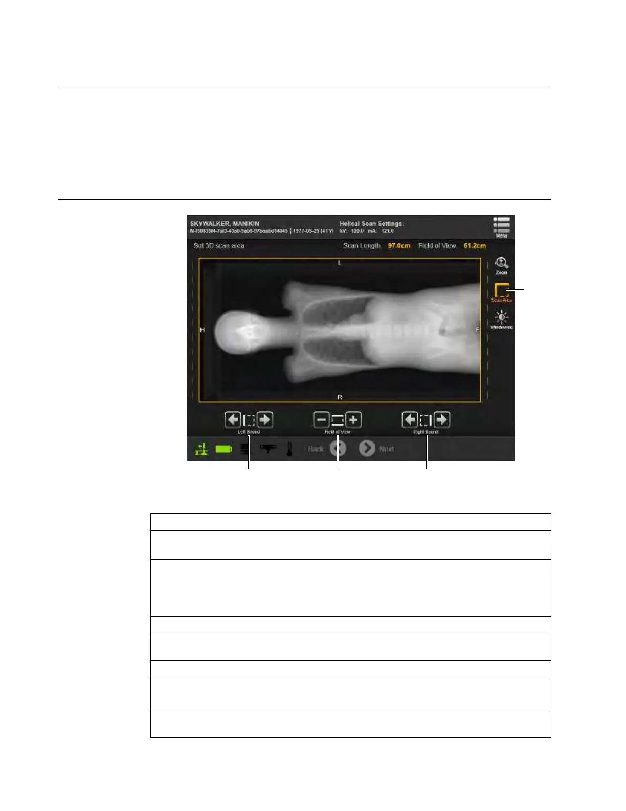
6.8.15 Selecting 3D Scan Region
Overview After verifying the parameters and running a Scout Scan, an image appears on the Pendant screen.
On-screen controls set viewing options and adjust the scan area for the 3D scan.
NOTES:
• The DICOM Viewer is used only for optimizing DFOV and evaluating the image. Use an
external diagnostic viewing device that meets local regulatory requirements when examining
images for diagnostic purposes.
• A fixed open collimator is used for both the CT scan and the optional scout scan.
How to Select a 3D
Scan Re
gion
Figure 82
Steps
1. Verify that the DICOM tags in the image for Head, Foot, Left, and Right (H,F,L,R) or Head,
Foot, Anterior, and Posterior (H, F, A, P) are correct in relation to the patient’s position.
2. If necessary adjust the contrast and magnification to locate the anatomical region of
interest.
• To adjust contrast, see the section How to Adjust Scout Scan View Settings below.
• To adjust magnification, see the section How to Zoom below.
3. Select
Scan Area
a. See Figure 82.
4. Set the length of the 3D scan using arrow buttons to manipulate both the Left Bound s and
the Right Bound d of the region. The minimum Helical scan length is 7.9cm (3.11 in.).
5. Adjust the Field of View of the 3D scan using the +/- Field of View buttons f.
6. Touch and release a button to move a setting by increments.
Press and hold it to move the setting faster.
7. After making all view settings and scan region adjustments (see Figure 83), touch
Next
to
proceed. See section 6.8.16 Selecting a Constant or Modulated Scan.