MI-42-0001 Rev. 19 237
CT USER INFORMATION: Dosage Factors and Image Quality
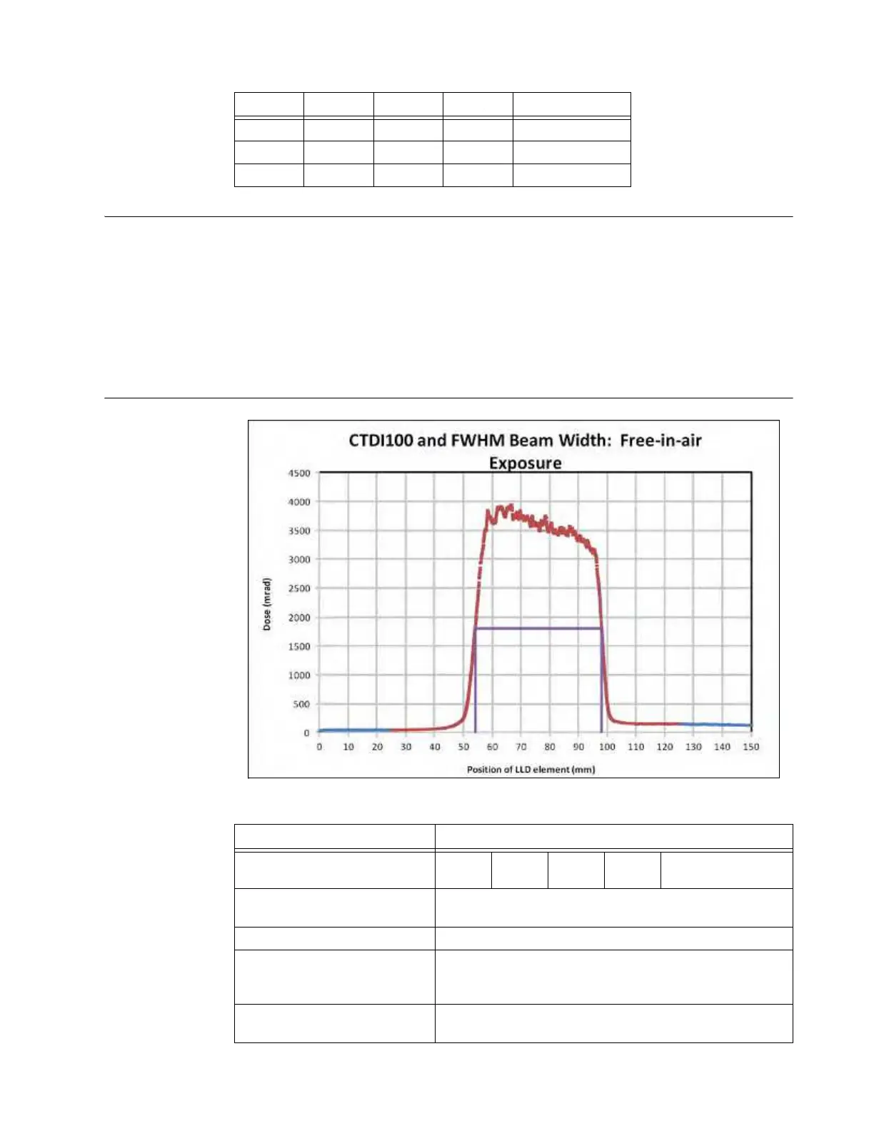
Dose Profiles
Technique Factors
Dose profiles were obtained by exposing Laser Luminescent Dosimeter (LLD) rods obtained from,
and analyzed by, Landauer, Inc., Chicago, IL. A plot of the dose profile at
isocenter, in free air during
one axial scan is presented.
The exposure was made at 120 kV, 25 mA, 2 sec (50 mAs), in the absence of the patient table. The
LLD rod, which uses Optically Stimulated Luminescence (OSL) technology, has an active
length of
150 mm. Exposure is presented in units of dose (mrad) at intervals of 0.05
mm, resulting in 3000
data points. Thickness of the radiation beam was calculated as 44
mm at full-width half maximum
(FWHM). CTDI
100
free air
was calculated using the integral of the dose profile over the central 100
mm span of the LLD. When extrapolated to 196
mAs, the CTDI
100
free air
obtained is 49.65 mGy.
Dose Profile: CTDI
Free-in-Air
Exposure
Figure 164
kV
mA sec mAs CTDI
100,
mGy
80 100 1.92 192 21.13
100 100 1.92 192 35.47
120 100 1.92 192 52.00
Variable Value
Free Air at Isocenter
120
kVp
100m
A
1.92
sec
192
mAs
Nominal Beam
Width 33.9
Max dose: Mean over position
range 57 to 93
3630.17 mrad
Half max dose 1815.08 mrad
Beam Thickness at Full Width
Half Maximum (FWHM)
position range 54 to 98
43.9 mm
Exposure length Integral
(central 100 mm)
165031.03 mrad-mm