6 Mounting
Maschinenfabrik Reinhausen GmbH 2020 673587317/21 EN TAPCON
®
Interface Pin Description
1 6 11 16 I OUT (+): Current output +
2 7 12 17 I/U IN (+) U OUT (+): Voltage input
+, current input +, voltage output +
3 8 13 18 I/U IN (-): Voltage input -, current in-
put -
4 9 14 19 I/U OUT (-): Voltage output -, current
output -
5 10 15 20 Not used
Table16: Analog inputs and outputs
You can connect the following types of analog sensors:
▪ 0/4...20mA
▪ 0...10V
▪ PT100/PT1000 (2-wire, 3-wire, 4-wire)
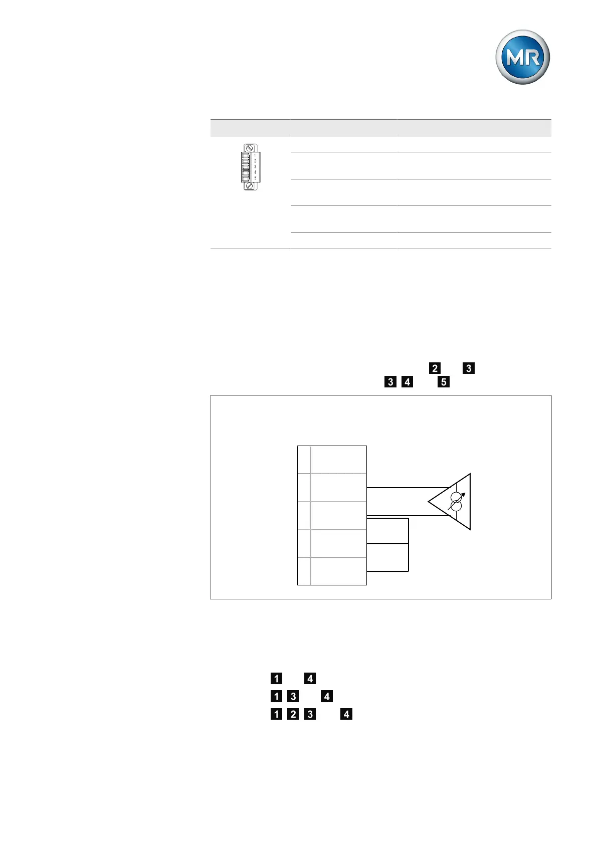
0/4...20 mA sensor
You must connect a 4...20 mA sensor to the pins and . You must also
connect the supplied bridge to the pins , , and .
I OUT (+)
I/U IN (+)
U OUT (+)
I/U IN (-)
I/U OUT (+)
1
2
3
4
5
---
4...20 mA signal source
Figure53: Connection example for a 4...20 mA sensor
PT100/PT1000 sensor
Depending on type, you must connect a PT100 sensor or PT1000 sensor as
follows:
▪ 2-wire: pin and
▪ 3-wire: pin , and
▪ 4-wire: pin , , , and