43967002TH Rev.1
381 /
Oki Data CONFIDENTIAL
8. Connection Diagrams
Unit Circuit diagram and configuration Part drawing Resistance value
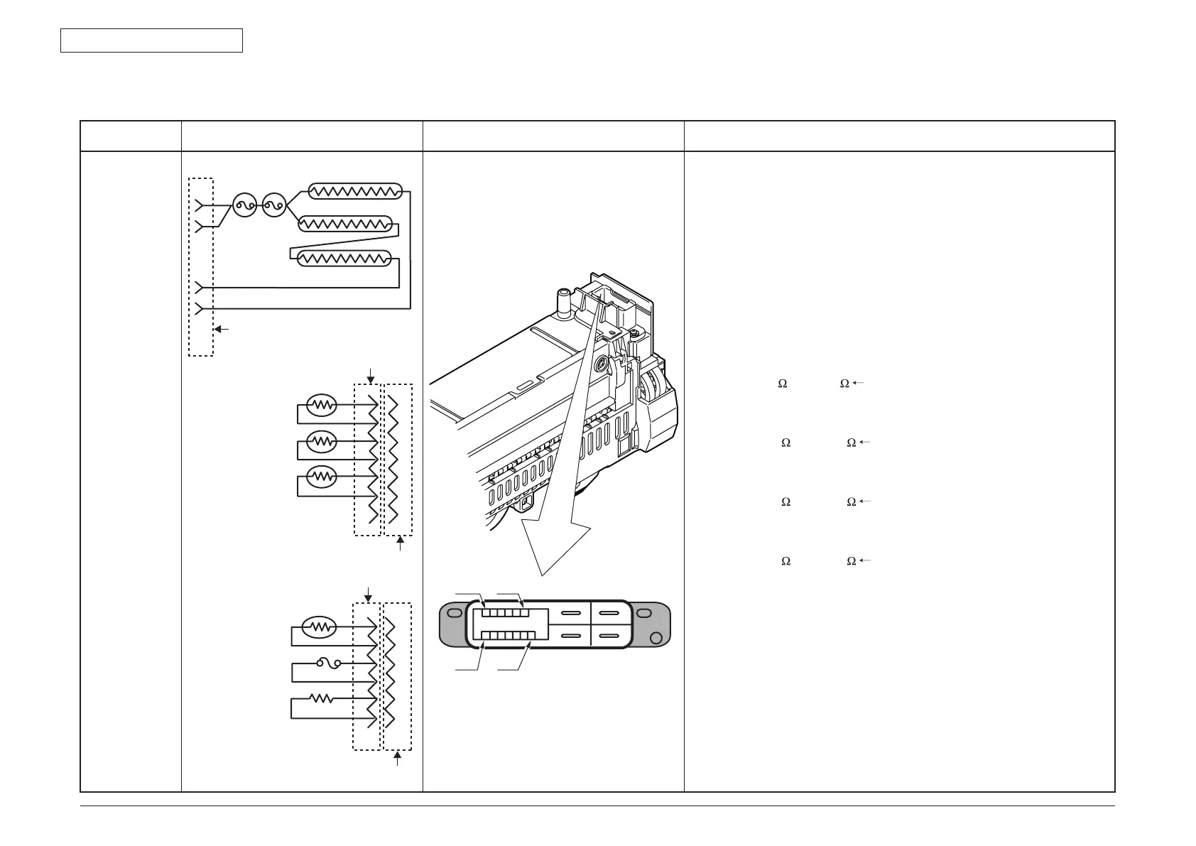
Fuser unit
1
2
3
4
5
6
7
A7
A6
A5
A4
A3
A2
A1
B6
B5
B4
B3
B2
B1
1
2
3
4
5
6
Upper #2 350W
Upper #1 800W
Lower 50W
3
1
2
4
13P-RWZV-K4GG-P4
13P-RWZV-K4GG-P4
CZHR-07V-S
CZHR-06V-S
13P-RWZV-K4GG-P4
Compensation
thermistor
(PT3-312)
Upper side
thermistor
(PT7-312)
Upper center
thermistor
(PM9-342)
Lower thermistor
(PT5-312)
Fuse
(For revision)
Thermostat
Between pin A-6 and pin A-7:
Approx. 8058 k
to 5338 k Upper center thermistor
( 0~93˚C)
Between pin A-2 and pin A-3:
Approx. 104.5 k
to 806.5 k Upper side thermistor
( 0~43˚C)
Between pin B-5 and pin B-6:
Approx. 104.5 k
to 806.5 k Lower thermistor
( 0~43˚C)
Between pin A-4 and pin A-5:
Approx. 104.5 k
to 806.5 k Compensation thermistor
( 0~43˚C)