WWW.NNC.IR
Alignment
315
8
Appendices
Vision System FH/FZ5 Series
User’s Manual (Z340)
Other Alignment Functions
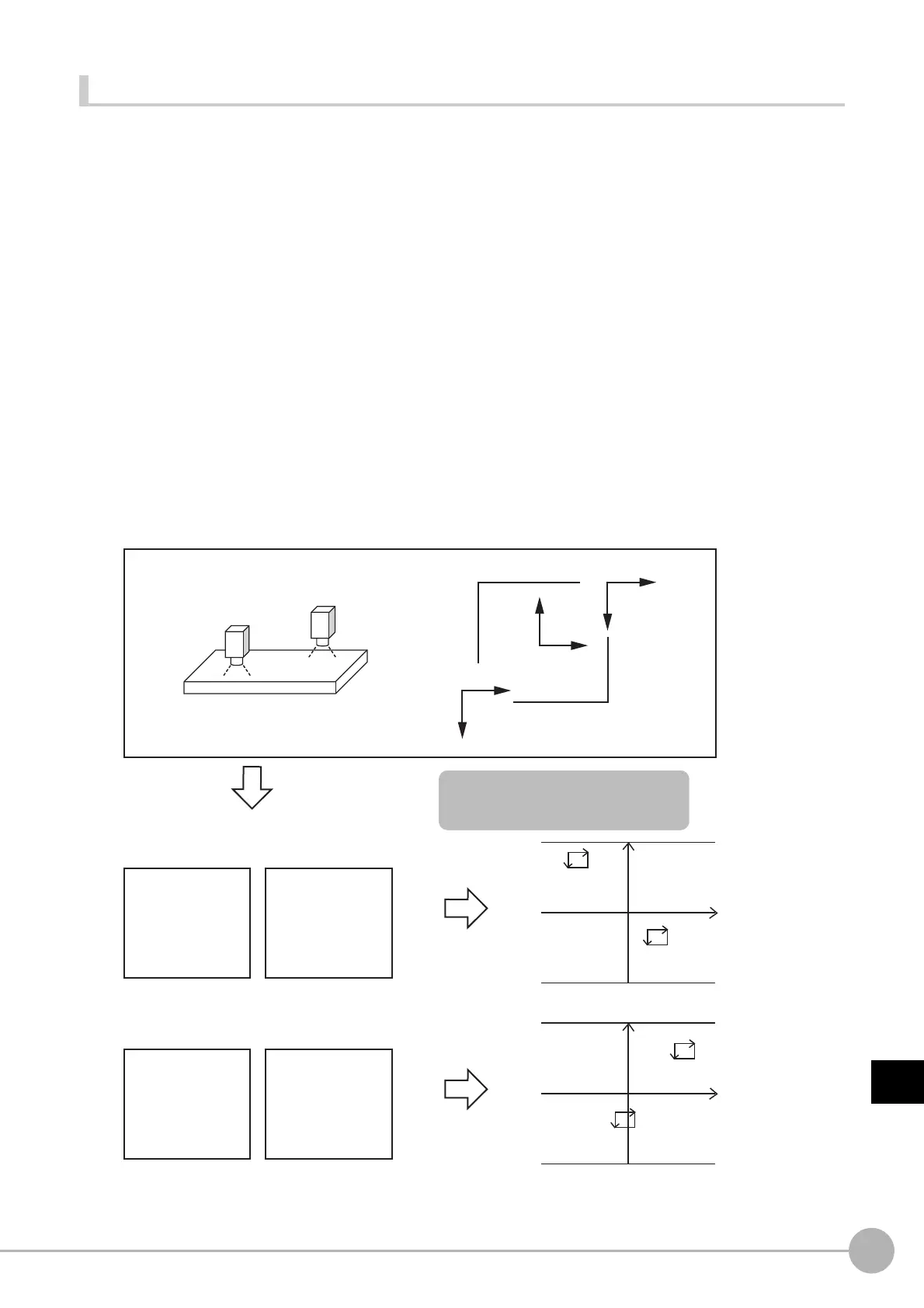
● Checking the Calibration Results
The Calibration Support Tool uses the calibration parameters to graphically display the relationship of the positions
that are represented by the Camera coordinates and the actual coordinates. You can compare the relationship of
the displayed position with the actual position of the equipment. This allows you to easily check the validity of the
calibration parameters. To start the Calibration Support Tool, select [Calibration support tool] from the [Tool] menu.
• Overview
The calibration data for the specified data number that is stored in the processing unit for the specified unit
number is used to graphically display the positioning relationship of the Camera coordinates and the
actual coordinates.
You can specify the following processing items for the processing units
• Camera Image Input
• Camera Image Input HDR
• Camera Image Input HDR Lite
• Camera Image Input FH
• Vision Master Calibration
• PLC Master Calibration
• Camera Calibration
• Reference Calib Data
• Precise Calibration
Camera 1 X
X
Y
Y
Camera 0 X
Y
Stage coordinates
Camera 0 Camera 1
A = 0.2500
B = 0.0000
C = −480.0000
D = 0.0000
E = −0.2500
F = 480.0000
A = 0.2500
B = 0.0000
C = 160.0000
D = 0.0000
E = −0.2500
F= −160.0000
Generate calibration
parameters
Graphic display
Calibration succeeded.
0
0
1
1
Calibration failed.
Camera 0 Camera 1
A = 0.2500
B = 0.0000
C = 480.0000
D = 0.0000
E = −0.2500
F = 480.0000
A = 0.2500
B = 0.0000
C = −120.0000
D = 0.0000
E = −0.2500
F = −120.0000
Graphic display
A comparison of the device drawings
and the graphic display will easily show
calibration errors.

 Loading...

