Home
Omron
Industrial Equipment
SYSMAC FH Series
Omron SYSMAC FH Series User Manual
5
of 1
of 1 rating
882 pages
Give review
Manual
Specs
To Next Page
To Next Page
To Previous Page
To Previous Page
Loading...
WWW.NNC.IR
Displaying and Checking
Processing Branches in a Scene
59
2
Setting Scenes (Me
asurement Flows)
Vision System FH/FZ5 Series
User’s Manual (Z340)
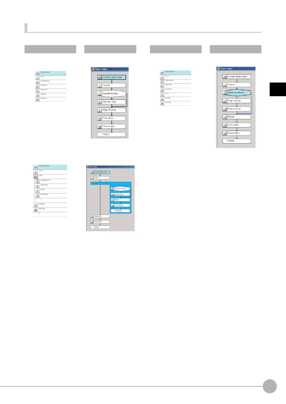
Examples of Branch and Folder V
iews
Examples:
Edit Flow Win
dow
Flow Viewer
Edit Flow Window
Fl
ow Viewer
Conditional Branch View
Selective Branch
⇒⇒
Folder View
⇒
60
62
Table of Contents
Default Chapter
3
FH/FZ5 Manual Configuration
3
Conventions Used in this Manual
3
Definitions of Basic Terms
4
Table of Contents
9
Terms and Conditions Agreement
15
Meanings of Signal Words
17
Precautions for Safe Use
19
Precautions for Correct Use
20
1 Before Operation
23
Overview
24
Basic Mechanism for Measurements
24
Support for a Variety of Scenes and Measurement Lines
25
Flow of Application
27
Windows
29
Types of Windows
29
Overview of Window Navigation
30
Main Window (Layout 0): Adjustment Window (Default)
31
Main Window (Layout 1): Run Window (Default)
37
Menu List
38
Checking the System Configuration
40
System Configuration
40
Basic Configuration Models
41
Functional Comparison between the FH-Series and FZ5-Series Controllers
44
Saving Settings before Turning off the Power and Restarting
45
Restarting the Controller: [System Restart]
45
Turning off the LCD
46
Initializing the Controller
47
Initializing the Controller: [System Initialization]
47
2 Setting Scenes (Measurement Flows)
49
What Is a Scene
50
Example of a Scene
51
What Is a Scene Group
53
Creating a Scene
54
Editing Processing Units in Scenes
55
Displaying and Checking Processing Branches in a Scene
58
Changing the Scene or Scene Group
62
Changing the Scene
62
Changing Scene Groups
62
Editing Scenes
64
Copying Scenes
64
Deleting Scenes
64
Renaming a Scene and Adding a Description
65
Editing Scene Groups
66
Copying and Deleting Scene Groups
66
Changing the Scene Group Name
67
3 Performing Test Measurement/Starting Operation
69
Adjustment Windows and Run Windows
70
Main Window (Layout 0): Adjustment Window (Default)
70
Main Window (Layout 1): Run Window (Default)
71
Main Window (Layout 1): Changing to the Run Window
71
Main Window (Layout 1): Changing to the Adjustment Window
71
Preparing the Controller and Cameras
72
Camera Setup
72
Preparing a Controller
73
Adjusting the Camera
74
Intelligent Camera (with Lighting)
75
Executing Test Measurements
76
Key Points for Adjustment
77
Stabilizing Measurements
77
Shortening Processing Time
78
Arranging Windows
80
Arranging Window Elements (Layout Modification)
80
Setting the Behavior of Output Signals for each Layout (Layout Settings)
92
Changing Layout Numbers in the Main Window
92
Troubleshooting
93
Arranging the Window Display
94
Changing the Image Mode and Other Display Contents
94
Custom Dialogs
96
Flow of Use
96
Custom Dialog Tool
97
Launching Your Custom Dialog Box
110
Useful Functions for Operation
111
Remeasuring Saved Images
111
Improving Adjustment Efficiency
112
Changing Judgement Conditions Without Stopping Measurement
113
Changing Regions as a Batch [Shift Area]
114
Monitoring Measurement Value Trends
114
Logging Measurement Values and Measurement Images
115
Analyzing Logged Data
123
Clearing Measurement Results
124
Clearing Saved Images
125
Capturing Screen Images
125
Using the Operation Log
127
Operation Log Format
129
Saving Data to an External Device
130
4 Using Tools
133
Using NG Analyzer
134
Layout of NG Analyzer Window
135
Using Method of NG Analyzer
136
Updating the Reference Position
139
Using the User Data Tool
140
Setting Procedure for User Data
140
Creating Scene Group Data for more than 128 Scenes
142
Outputting a List of Scene Data Set Values
145
Downloading Set Values
145
About Downloaded CSV Files
145
Uploading Set Values
147
Saving Image Files to a RAM Disk or External Memory Device
148
Using the Registered Image Manager
150
Registering Images
150
Loading an Image
151
Using Accounts
152
Setting Accounts (Account List)
152
Setting Layout Restrictions
154
Setting User Group Operation Restrictions
155
Saving/Loading/Deleting the Security Settings
156
Changing between User Accounts
159
Logging in
159
Logging out
159
Remotely Operating the Controller (Remote Operation)
160
Overview
160
Operation Environment Condition
161
How to Start
163
Using Communication Command Macro
166
Flow Viewer
167
Custom Dialog Boxes
168
Calibration Support Tool
169
Saving Scene Groups in External Memory
170
5 Optimizing Scenes (Measurement Flows) (Macro Customize Functions)
173
Basic Knowledge for Macro Customize Functions
175
What Are the Macro Customize Functions
175
List of Macro Customize Functions
175
Structure of this Chapter
177
How to Use Macro Customize Functions
178
Components of the Macro Customize Functions
178
Procedures for Using the Macro Customize Functions
179
Components of the Screens and How to Configure Settings
183
Components of the Program Editing Screen
183
Description of the System Status Console Window
187
Description of the Setting Screen for the "Unit Calculation Macro" Processing Item and How to Configure Settings
188
Description of the Setting Screen of the Scene Control Macro Tool and How to Configure Settings
192
Components of the Setting Screen of the Communication Command Macro Tool and How to Configure Settings
194
Description of the Setting Screen of the "Unit Macro" Processing Item and How to Configure Settings
201
Saving and Loading Programs
205
Basic Method for Writing Programs
207
Basic Syntax
207
Constant
210
Variable
211
Operator
215
Expression
217
How to Write Advanced Programs
219
Data Types Related to Processing Units
219
Data Types Related to the System
224
Scope of Data and Save Area
227
State Transitions and Execution Timing
229
Exclusive Control in a Process
236
How to Use the Debug Function
237
Debug Preparations
237
Debug Procedure
240
Checking Why an Error Occurred
240
Starting Debug
242
Identifying the Cause of an Error
243
Removing the Error
246
Exiting Debug
246
Troubleshooting
247
6 Saving and Loading Data
255
Saving Data to the FH/FZ5
256
About Saving Areas
256
External Drive Names
257
Using External Memory Devices (FH and FZ5-11 Only)
258
Shared Folder on a Computer Connected to the Network
258
Saving Settings Data to the Flash Memory and Restarting
259
Saving Settings Data to the Controller RAM Disk or an External Memory Device
260
Saving Logged Images in the Controller Memory (RAM) to a RAM Disk or an External Memory Device
261
Copying or Moving Files between the Controller RAM Disk and an External Memory Device
262
Loading Settings Data from the Controller RAM Disk or an External Memory Device to the Sensor Controller
263
7 Changing the System Environment
265
Setting the Camera Conditions
266
Checking the Camera Connections: [Camera Connection]
266
Setting the Trigger Delay: [Inter-Camera Setting]
266
Setting the SHTOUT Signal: [Output Signal Settings]
267
Setting the Conditions that Are Related to Operation During Measurement
269
Setting the Operation Mode
270
Guidelines for Selecting the Operation Mode
270
Single-Line High-Speed Mode
271
Multi-Line Random-Trigger Mode
275
Non-Stop Adjustment Mode
281
High-Speed Logging Mode
283
Parallel Processing
284
Parallel Processing Settings (Automatic Parallelization)
284
Parallel Processing Settings (Manual Parallelization)
284
Specific Example of Parallel Processing
286
Restrictions
287
Setting Procedures
289
Setting the Operating Environment of the System
293
Setting the Date and Time: [Date-Time Setting]
293
Selecting the Language: [Language Setting]
294
Setting the Fan Rotation Speed: [Fan Control Setting]
294
Setting the Status at Startup: [Startup Settings]
295
Setting the Encoder Trigger: [Encoder Trigger Setting]
298
Setting the STEP Input Detection Pulse Width: [STEP Setting]
299
Setting a Network Drive: [Network Drive Setting]
300
Checking System Information: [System Information]
302
8 Appendices
303
Alignment
304
Overview
304
Execution of Calibration
307
Troubleshooting
313
Alignment
314
Alignment Processing Items
321
Macro Reference
322
Error List
322
List of Reserved Words
324
System Data List
329
List of I/O Modules
343
List of Figure Numbers
368
Model Number List
371
Image Number List
373
List of Sub-Image Numbers
376
Memory Usage Guidance for Processing Items
381
Macro Function List
386
Function-Based Index
397
Macro Command Reference
405
About Lenses
813
Error Messages and Troubleshooting
829
Faq
833
During Start-Up
833
During Operation
833
For Measurement
834
About Parallel Interface
835
Serial Interface (RS-232C/422 Connection)
836
Camera with Lighting Controller
836
Measurement Mechanism
837
Color Processing Mechanism
837
Search Processing Mechanism
838
Edge Detection Measurement
841
Defect Detection Measurement
844
Handling Coordinates
844
Basic Knowledge about Operations
846
Inputting Values
846
Inputting Text
846
Selecting Files and Folders
847
Available Operations in Select File Window
848
Using the Zoom Function
849
Layout of Figure Setting Area
850
Setting Figures
850
Setting Methods
851
About or Setting/Not Setting
857
About Number of Logging Images
858
About Limits on the Number of Image Input Processing Items Used
860
About Max. Number of Loading Images During Multi-Input
861
Character Code Table
862
About Memories Usable with FZ Series
863
Memory Display Image on PLC I/O
864
Operation Log Input Information List
866
Manual Revision History
880
Other manuals for Omron SYSMAC FH Series
Hardware Setup Manual
260 pages
Operation Manual
176 pages
5
Based on 1 rating
Ask a question
Give review
Questions and Answers:
Need help?
Do you have a question about the Omron SYSMAC FH Series and is the answer not in the manual?
Ask a question
Omron SYSMAC FH Series Specifications
General
Brand
Omron
Model
SYSMAC FH Series
Category
Industrial Equipment
Language
English
Related product manuals
Omron FH-5550
248 pages