WWW.NNC.IR
Macro Reference
700
Vision System FH/FZ5 Series
User’s Manual (Z340)
SetDrawStyle
Set the drawing attributes of the graphic figure.
Format
SetDrawStyle <style>, <width>, <color>
Parameter
Return value
None.
Description
Sets the specified line type by the <style> parameter, the specified line width by the <width> parameter, and
specified line color by the <color> parameter as the drawing attributes. Before executing the image screen
window control macro function that draws graphic figure, execute this macro function to draw the graphic
figure using the set drawing attribute. Use the SetTextStyle function to set the drawing attribute used for the
DrawTextG function. (Reference: XSetTextStyle (p.727))
If any of "PS_DASH", "PS_DASHDOT", and "PS_DASHDOTDOT" is specified in the <style> parameter,
specify 1 in the <width> parameter. If other than 1 is specified, a solid line will be drawn.
If circle, wide circle, ellipse, arc, wide arc is drawn with specification of "PS_INSIDEFRAME" for the <style>
parameter, the figure with specified line width by the <width> parameter is drawn and diminished so that the
drawn figure is within the figure. Other figure types than ones mentioned above are drawn with a solid line
(i.e., the same line type as when "PS_SOLID" is specified for the <style> parameter).
The gotten color value by the RGB function can be set for the <color> parameter. (Reference: XRGB (p.662))
If an incorrect data type is specified for a parameter, a "Type mismatch" error will occur.
If a value outside the range -2147483648 to 2147483647 is specified as an integer parameter, an "Overflow"
error will occur.
If the format is written incorrectly, such as writing the macro function name incorrectly, omitting a comma, or
omitting a half-width space, a "Syntax error" error will occur.
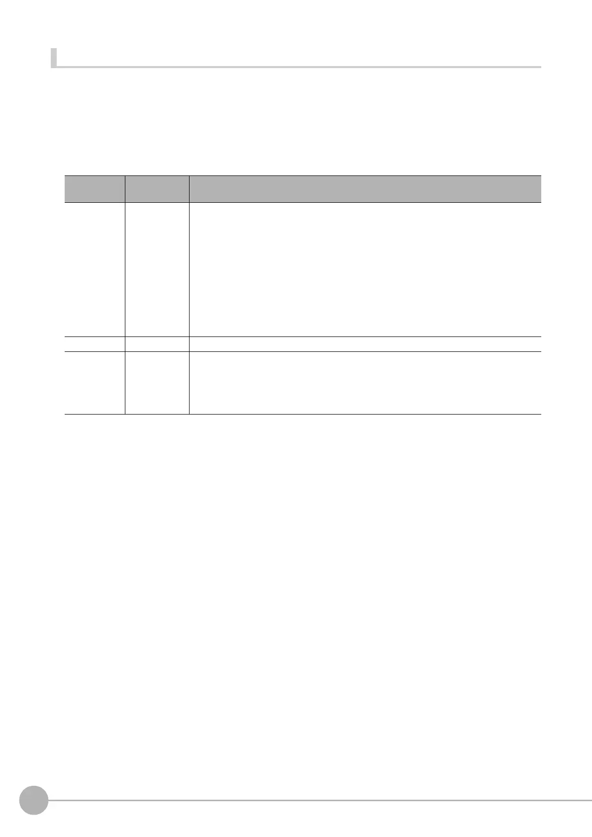
Parameter
name
Data type Description
<style> Integer type
Type of the drawn line
PS_SOLID: Solid line
PS_DASH: Dashed line (This selection is valid only when the specified line width is 1)
PS_DOT: Dotted line
PS_DASHDOT: One-dot chain line (This selection is valid only when the specified line
width is 1)
PS_DASHDOTDOT: Two-dot chain line (This selection is valid only when the specified
line width is 1)
PS_NULL: No line
PS_INSIDEFRAME: Solid line (This selection is only valid for circle, wide circle, ellipse,
arc, and wide arc)
<width> Integer type Line width of the drawn graphic line
<color> Integer type
Line color value of the drawn graphic line
JUDGE_NC: Unmeasured color (Grey)
JUDGE_OK: OK judgement color (Green)
JUDGE_NG: NG judgement color (Red)
RGB Function: Any color
 Loading...


