15-22
FP0R (A: Available, N/A: Not available)
Address Name Description
DT90022
Scan time (current
value)
Note)
The current scan time is stored here. Scan
time is calculated using the formula:
Scan time (ms) = stored data (decimal) x 0.1
ms
Example: K50 indicates 5 ms.
A N/A
DT90023
Scan time (minimum
value)
Note)
The minimum scan time is stored here. Scan
time is calculated using the formula:
Scan time (ms) = stored data (decimal) x 0.1
ms
Example: K50 indicates 5 ms.
A N/A
DT90024
Scan time (maximum
value)
Note)
The maximum scan time is stored here. The
scan time is calculated using the formula:
Scan time (ms) = stored data (decimal) x 0.1
ms
Example: K125 indicates 12.5 ms.
A N/A
DT90025
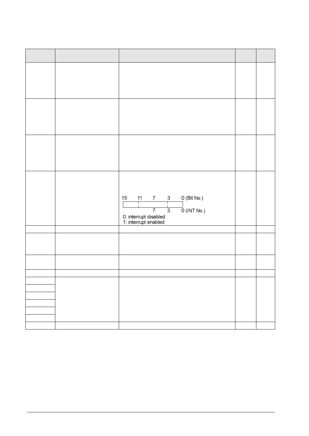
Mask condition
monitoring register
for interrupts
(INT0 to 11)
The mask conditions of interrupts using the
instruction can be stored here. Monitor using
binary display.
A N/A
- N/A N/A
DT90027
Periodical interrupt
interval (INT24)
The value set by ICTL instruction is stored.
K0: periodical interrupt is not used.
K1 to K3000: 0.5ms to 1.5s or 10ms to 30s
A N/A
DT90028 Sample trace interval
K0: Sampling by the SMPL instruction
K1 to K3000 (x 10 ms): 10 ms to 30 s
A N/A
Character storage by
F149 MSG instruction
The contents of the specified message (Data
length) are stored in these special data
registers when F149 (MSG) instruction is
executed.
A N/A
- N/A N/A
Note) Scan time display is only possible in RUN mode, and shows the operation cycle time. (In PROG.
mode, the scan time for the operation is not displayed.) The maximum and minimum values are
cleared each time the mode is switched from RUN to PROG.