Communication
C3I10T10
192-120100 N16 C3I10T10 - December 2010
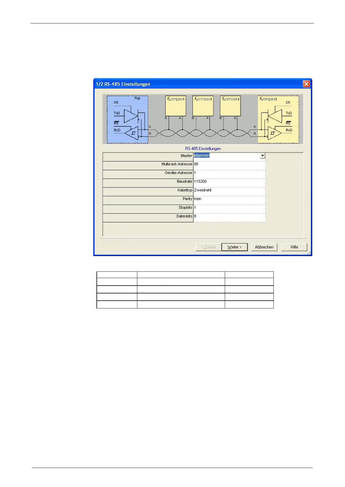
5.1.7. C3 settings for RS485 two wire operation
C3 ServoManager RS485 wizard settings:
download with configuration in RS232 mode°!
Communication settings C3S/C3M:
810.1 Protocol 16 (two wire)
810.2 Baud rate 115200
810.3 NodeAddress 1..254
810.4 Multicast Address
 Loading...


