Parker EME
Compax3 device description
192-120100 N16 C3I10T10 - December 2010
PSUP10: 2400 µF
Maximum capacity in the axis system:
PSUP20 & PSUP30: 5000 µF
100 µF per kW of the temporal medium value of the total power (transmissions +
power dissipation) in the axis system
Reference value for the required capacity in an axis system
Example: PSUP20 (1175 µF) with one axis controller (440 µF)
Total power 15 kW, 100 µF/kW => 1500 µF required in the axis system.
Axis system: 1615 µF are sufficient.
Protective seals
Caution!
The user is responsible for protective covers and/or additional safety measures in
order to prevent damages to persons and electric accidents.
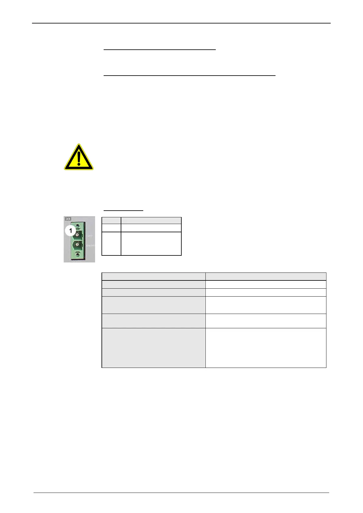
3.5.4. Control voltage 24VDC PSUP (mains module)
Connector X9
Line cross sections:
minimum: 0.5mm
2
with conductor sleeve
maximum: 6mm
2
with conductor sleeve
(AWG: 20 ... 10)
1 +24 V
2 GND24V
Control voltage 24 VDC PSUP
Voltage range
21 - 27VDC
Ripple
0.5Vpp
Requirement according to safe extra
low voltage (SELV)
yes (class 2 mains module)
Current drain PSUP
PSUP10: 0.2A
PSUP20 / PSUP30: 0.3A
Electric current drain Compax3M
C3M050D6: 0.85
3M100D6: 0.85A
C3M150D6: 0.85A
C3M300D6: 1.0 A
+ Total load of the digital outputs + current for
the motor holding brake
 Loading...


