Compax3 device description
C3I10T10
192-120100 N16 C3I10T10 - December 2010
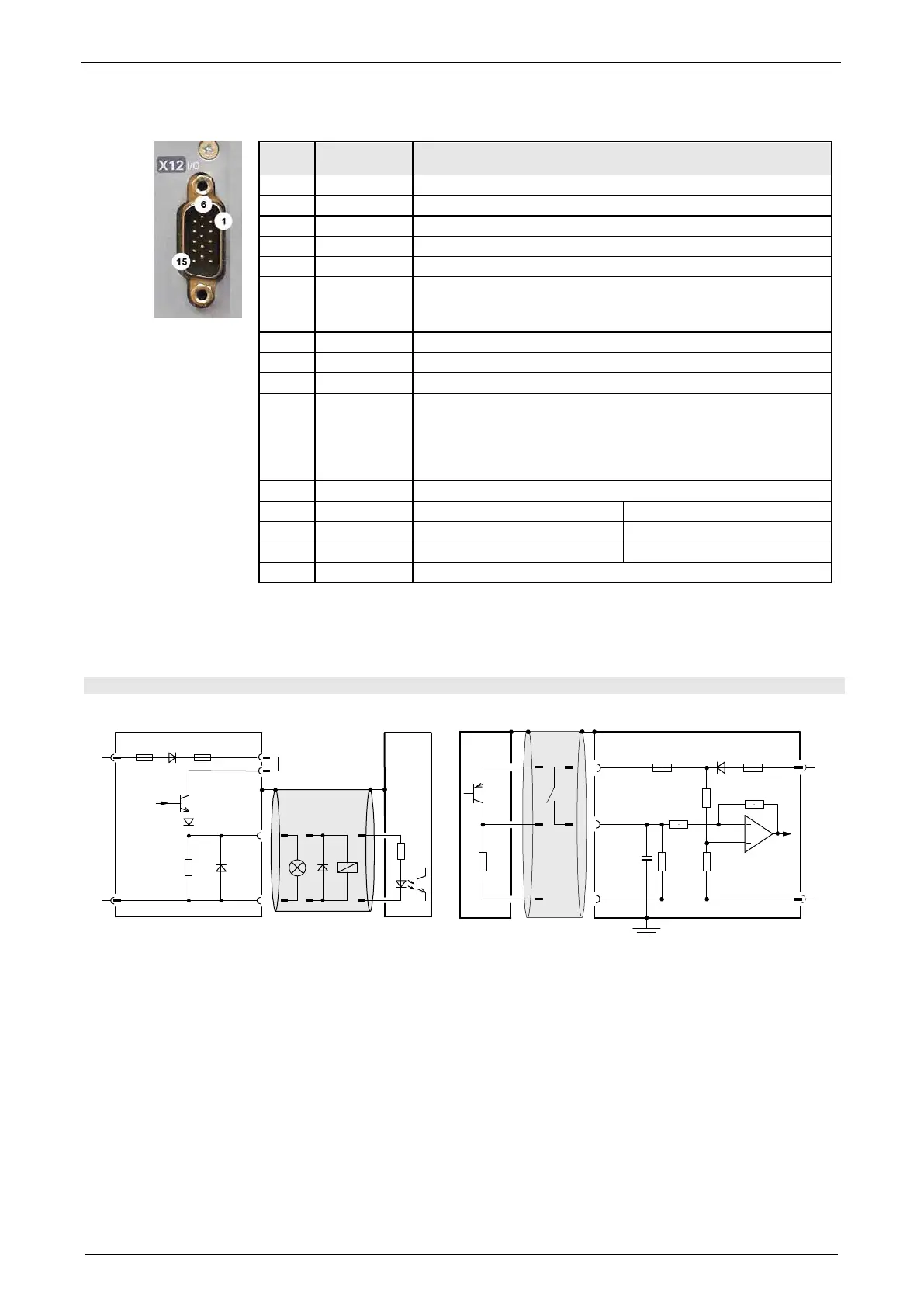
3.8.3. Digital inputs/outputs (plug X12)
I/O /X12
High density/Sub D
1 Output +24 V DC output (max. 400mA)
2 O0 = "1" no error (max. 100mA)
3 O1 = "1" Actual value in setpoint window (max. 100mA)
4 O2 = "1" Power stage without current (max.) 100 mA)
5 O3 = "1" Motor energized with a setpoint of 0 (max. 100 mA)
6 I0 = "1"
Energize motor (see on page 65) & deactivate motor holding
brake (see on page 143)
Motor stationary in controlled state with setpoint = 0
7 I1 = "1" Enable Setpoint value
8 I2 = "1" Quit (positive edge)
9 I3 = "1" Open brake
10 I4 = "1" Keep position / speed 0 (configurable)
(only in the "±10V analog current" setpoint" (see on page
106)mode
Keep position / speed 0 (configurable)(only in the "±10V analog
(see on page 103)mode"
11 I 24V input for the digital outputs Pins 2 to 5
12 - n.c. Zero pulse
13 I Step input (24V level) A (24V level)
14 I Direction input (24V level) B (24V level)
15 Output GND24V
All inputs and outputs have 24V level.
Maximum capacitive loading of the outputs: 50nF (max. 4 Compax3 inputs)
3.8.3.1 Connection of the digital Outputs/Inputs
Wiring of digital outputs
24V
0V
X12/2
18.2K
Ω
X12/15
X12/1
X12/11
SPS/
PLC
F2
F1
Compax3
24V
0V
100K
Ω
X12/1
X12/6
X12/15
10K
Ω
22K
Ω
22K
Ω
22K
Ω
SPS/PLC
F2
F1
10nF
Compax3
The circuit example is valid for all digital outputs!
The outputs are short circuit proof; a short circuit
generates an error.
The circuit example is valid for all digital inputs!
Signal level:
> 9.15V = "1" (38.2% of the control voltage applied)
< 8.05V = "0" (33.5% of the control voltage applied)
F1: Delayed action fuse
F2: Quick action electronic fuse; can be reset by switching the 24 VDC supply off and on again.

 Loading...


