Parker EME
Compax3 device description
192-120100 N16 C3I10T10 - December 2010
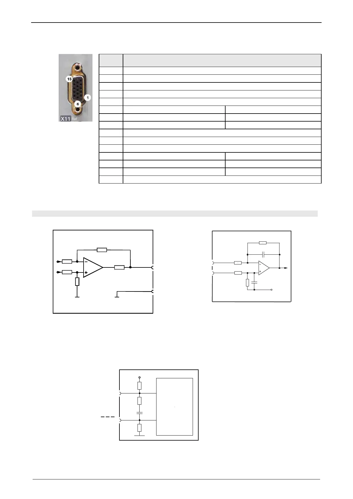
3.8.2. Analogue / encoder (plug X11)
Reference
High Density Sub D
1 +24V (output for encoder) max. 70mA
2 factory use
3 D/A monitor channel 1 (±10V, 8-bit resolution)
4 D/A monitor channel 0 (±10V, 8-bit resolution)
5 +5 V (output for encoder) max. 150 mA
6 - Input: steps RS422 (5V - level)
A/ (Encoder- input / -simulation)
7 + Input: steps RS422 (5V - level)
A (Encoder- input / -simulation)
8 + Input: direction RS422 (5V - level)
B (Encoder- input / -simulation)
9 Ain0 +: analog setpoint input + (14Bit; +/-10V)
10 factory use
11 Ain0 -; analog setpoint input - (14Bit) +/-10V)
12 - Input: direction RS422 (5V - level)
(Encoder- input / -simulation)
13 factory use
N/ (Encoder simulation)
14 factory use
N (Encoder simulation)
15 GND
Encoder simulation exists with an analogue input command interface of ±10V.
3.8.2.1 Wiring of analog interfaces
Compax3
+/-10V/1mA
(max: 3mA)
X11/3
X11/15
332
Ω
X11/4
10nF
2.2KΩ
10KΩ
Ain+
2.2KΩ
X11/9
10KΩ
10nF
Ain-
X11/11
2.5V
Compax3
Perform an offset adjustment (see on page 142)!
Structure image of the internal signal processing of the analog inputs
3.8.2.2 Connections of the encoder interface
10nF
+5V
121
Ω
A
1K
Ω
1
K
Ω
GND
A B N
RS422
Transceiver
B N
Compax3
The input connection is available in triple (for A & /A, B & /B, N & /N)

 Loading...


