Parker EME
Compax3 device description
192-120100 N16 C3I10T10 - December 2010
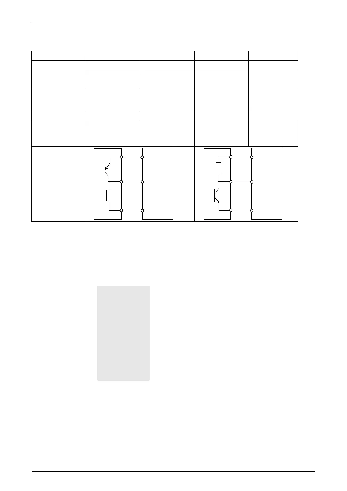
3.8.3.2 Logic proximity switch types
Type 1 2 3 4
Transistor switch PNP PNP NPN NPN
Logic (N.O.)
“active high"
(N.C)
“active low"
(N.O.)
“active low"
(N.C)
“active high"
Description of logic Compax3 sees a
logical “1” upon
activation
Compax3 sees a
logical “0” upon
activation"
Compax3 sees a
logical “0” upon
activation"
Compax3 sees a
logical “1” upon
activation
Fail safe logic no yes Only conditional
1)
no
Instruction for pull
up resistor in the
initiator
- - Rmin=3k3
Rmax=10k
2)
Rmin=3k3
Rmax=10k
2)
Connections
X12/1 (+24 VDC)
X12/15 (GND)
X12/X (Input)
X12/1 (+24 VDC)
X12/15 (GND)
X12/X (Input)
1)
When the connection between transistor emitter of the initiator and X12/15
(GND24V of the Compax3 )is lost, it can not be guaranteed, that the Compax3
detects a logical „0".
2)
The INSOR NPN types INHE5212 and INHE5213 manufactured by Schönbuch
Electronic do correspond to this specification.
3.8.3.3 Energize motor X12/6="24VDC"
This input effects the state of the power stage and therefore that of the motor:
De-energize motor
With a rotating motor, this will be decelerated to a speed of 0 via
a settable deceleration ramp.
Thereafter current switch-off and activation of the motor
holding brake (see on page 143).
Energize motor
Motor holding brake is deactivated (see on page 143), current
is applied to the motor and the motor is accelerated to the
commanded speed setpoint via an adjustable accelerating ramp.
Prerequisite: X12/7 "Enable setpoint" = 24VDC
In response to X12/7 "Enable setpoint" = 0VDC the control loop
adjusts to setpoint = 0.
Setting values for "Energize motor"
See also Setpoint control (see on page 107).

 Loading...


