Parker EME
Compax3 device description
192-120100 N16 C3I10T10 - December 2010
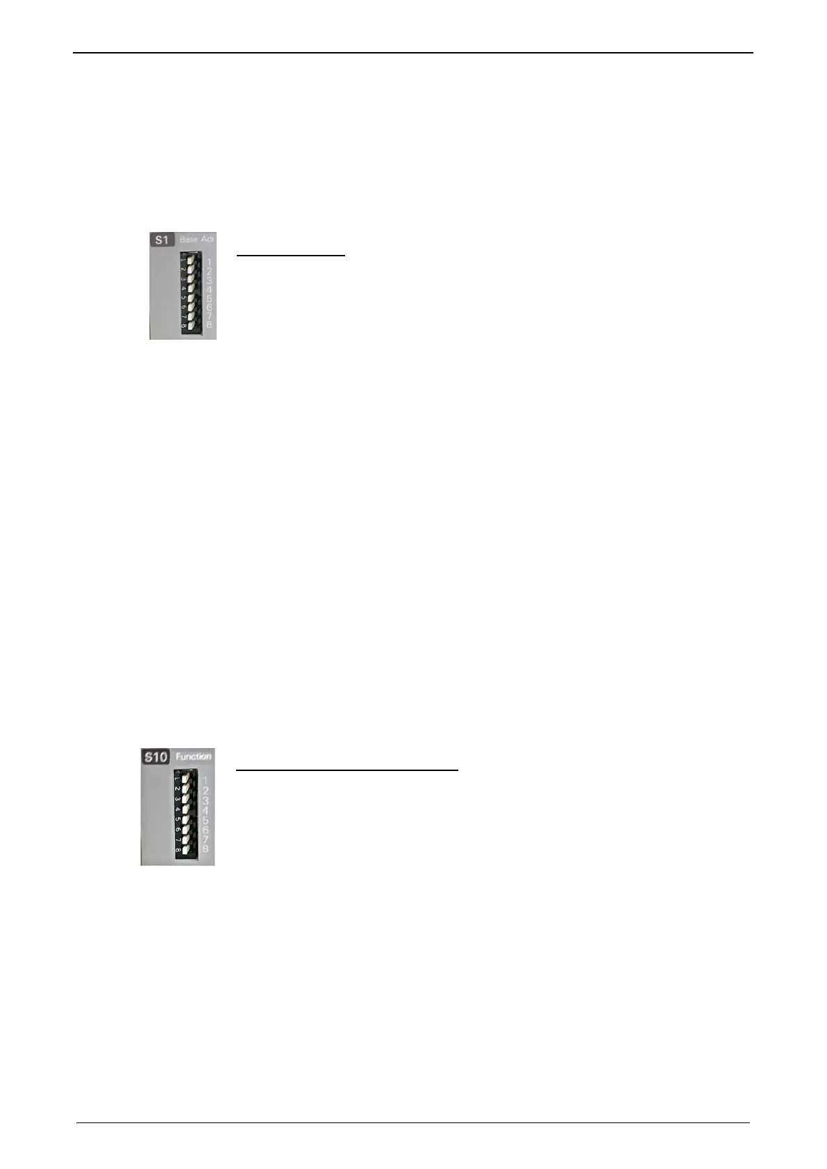
3.7.2.3 Adjusting the basic address
On the mains module, the basic address of the device combination is set in steps
of 16 with the aid of the first three dip switches.
The mains module contains the set basic address while the axes placed at the right
in the combination contain the following addresses.
Switch S1
Basic addresses
Address setting
1 16
2 32
3 64
Settings:
left: OFF
right: ON
Settable value range: 0, 16, 32, 48, 64, 80, 96, 112
Address of the 1st axis = basic address+1
The addresses of the axis controllers are newly assigned after PowerOn.
Example:
Basic address = 48; mains module with 6 axis controllers in the combination
1. Axis right: Address = 49
2. Axis right: Address = 50
...
6. Axis right: Address = 54
3.7.2.4 Setting the axis function
Switch S10
The value of switch S10 on the axis controller is stored in object O110.1
C3plus.Switch_DeviceFunction and can be evaluated with the aid of a program.
Function settings for T30 and T40
This helps realize a more simple function selection.

 Loading...


