Parker EME
Compax3 device description
192-120100 N16 C3I10T10 - December 2010
3.10.2. STO (= safe torque off) with Compax3S
STO Principle (= Safe Torque Off) with Compax3S
In this chapter you can read about:
......................................................... 79
Conditions of utilization STO (=safe torque off) Safety function ....................................... 81
Notes on the STO function .............................................................................................. 81
STO application example (= safe torque off) ................................................................... 83
Technical Characteristics STO Compax3S ..................................................................... 86
3.10.2.1 STO Principle (= Safe Torque Off) with Compax3S
To ensure safe protection against a motor starting up unexpectedly, the flow of
current to the motor and thus to the power output stage must be prevented.
This is accomplished for Compax3S with two measures independent of each other
(Channel 1 and 2), without disconnecting the drive from the power supply:
Channel 1:
Activation of the power output stage can be disabled in the Compax3 controller by
means of a digital input or with a fieldbus interface (depending on the Compax3
device type) (deactivation of the energize input).
Channel 2:
The power supply for optocouplers and drivers of power output stage signals is
disconnected by a safety relay activated by the enable input "ENAin"(X4/3) and
equipped with force-directed contacts. This prevents control signals from being
transferred to the power output stage.
The STO (= Safe Torque Off) safety function in accordance with EN ISO
13849-1: 2008 PLd or PLe, Kat.3 is only possible when using both channels
via an external safety switching device
Please note the application examples!
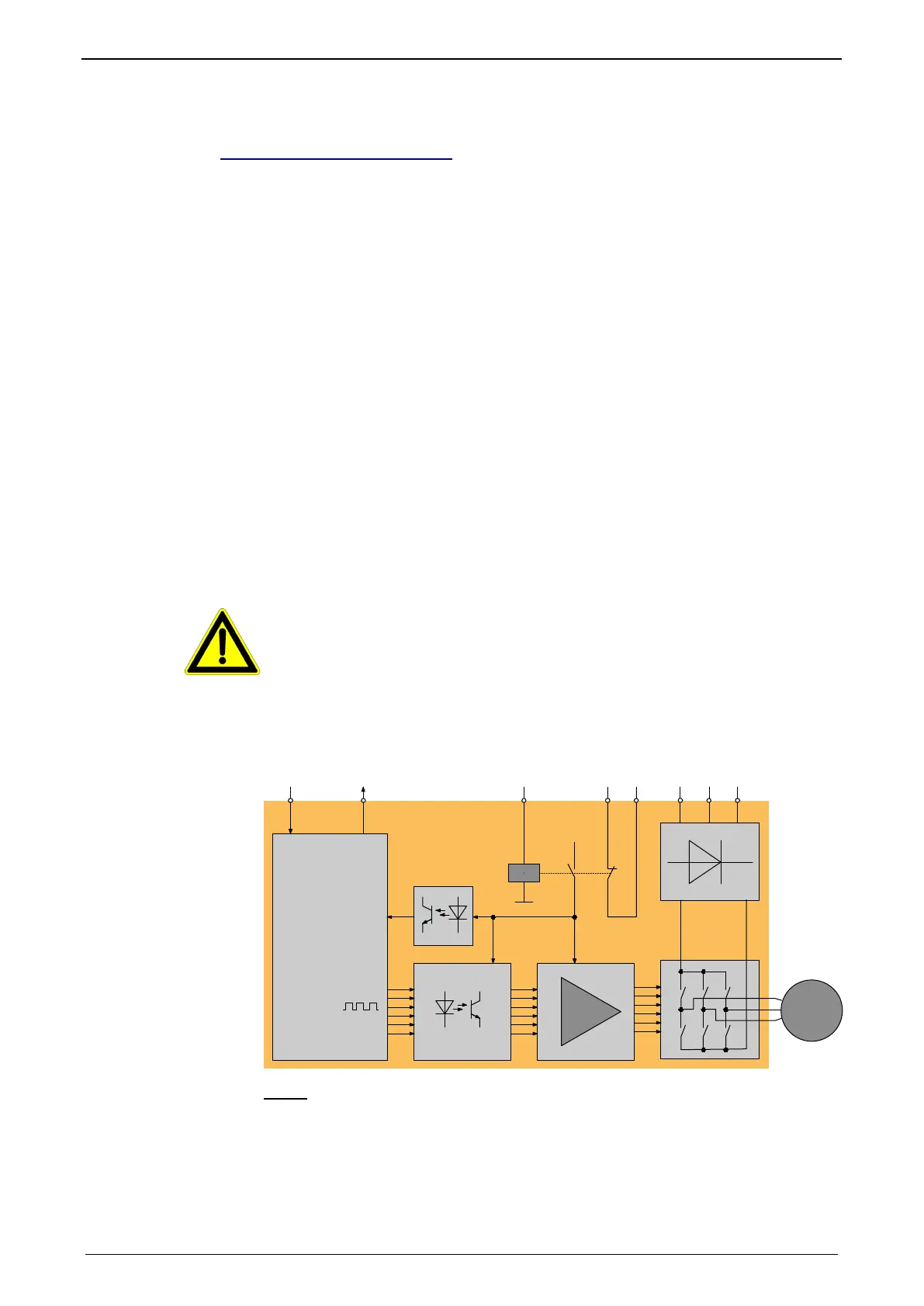
Circuit diagram illustrating working principle:
controller
safety relay
X4/3 X4/5X4/4
X1/1 X1/2 X1/3
Feedback
power
supply
power
supply
motor
Channel 1 Channel 2
L1 L2 L3
Energize
Controller
Feedback
ENAin
(Enable)
Feedback
Compax3
In normal operation of Compax3, 24VDC of power is supplied to the "Enable"
input (X4/3). The control of the drive takes then place via the digital inputs/outputs
or via the fieldbus.
Notes

 Loading...


