Parker EME
Setting up Compax3
192-120100 N16 C3I10T10 - December 2010
4.2 Test commissioning: Compax3 S0xx V2 I10
Analog command interface +/-10V with encoder simulation
In this chapter you can read about:
........................................... 112
Step/Direction Input RS422 ........................................................................................... 112
Encoder input RS422..................................................................................................... 112
Encoder input 24V ......................................................................................................... 113
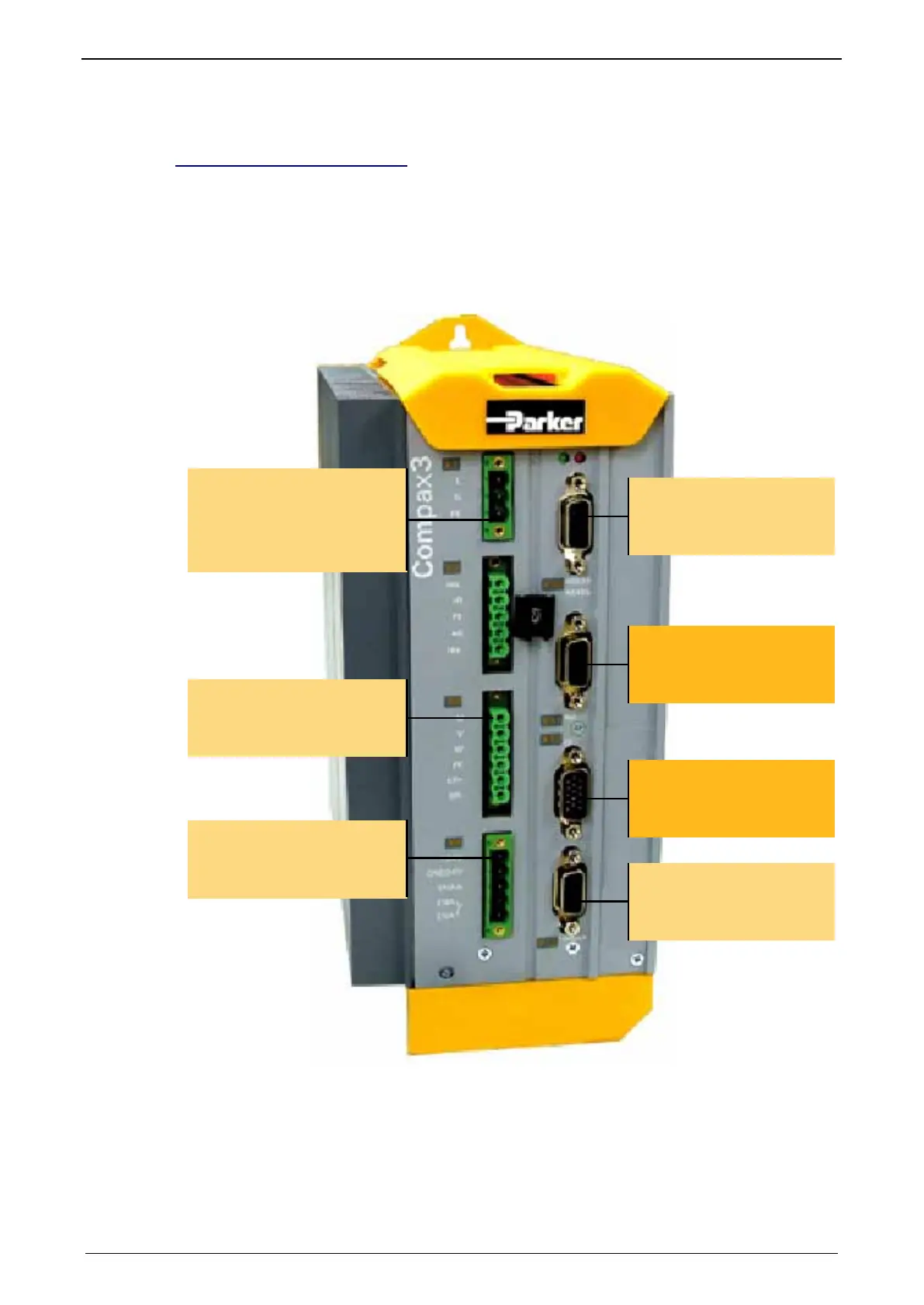
For testing and understanding the function of the device, the required input
connections are specified below for making simple movements.
Required wiring:
X4: 24VDC
/3: Enable with 24VDC
X3
Motor / Brake
X1: Mains supply
/1: 230V AC +10%
/2: 0V
/3: PE
X13 to
Motor-Feedback
X12: (see following)
Inputs/Outputs
X10 to PC
RS232 / RS485
X11: (see following)
Analogue/Encoder
 Loading...


